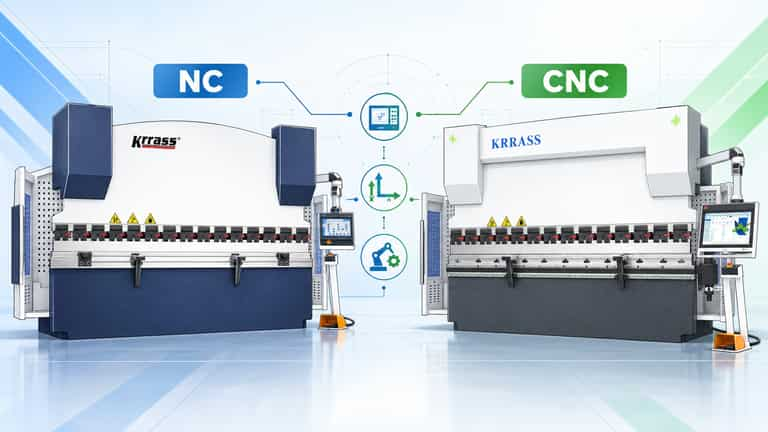
When comparing a CNC press brake vs NC press brake, the important question is not which machine has a more attractive touchscreen. It is whether the machine can produce your actual parts, at the required quality, safely and at a commercially sensible cost. Two machines can both have electronic controllers and programmable backgauges while using very different mechanical and hydraulic architectures. Those differences can affect synchronization, angle consistency, setup time, tooling choices and future expansion.
An NC press brake is often the rational option for straightforward bending, stable work and limited capital budgets. A fully synchronized CNC press brake usually earns its premium when the factory processes many different jobs, needs repeatable multistep sequences or must control long bends and challenging geometries more consistently. Neither conclusion is automatic. Material, tooling, operator skill, guarding, machine condition and the contractually supplied configuration still determine the outcome.
This updated guide retains the original article’s useful explanations of applications, components, advantages and maintenance, but concentrates its additional depth on verifiable configurations, controller and machine interfaces, reproducible tonnage calculations, measurable acceptance tests and operating-cost evidence. Product specifications below are drawn from linked KRRASS product and family pages; controller capabilities are cross-checked against manufacturer documentation. Where numerical savings or process outcomes are simulated, they are identified as illustrative—not claimed factory test results.
Quick answer: Choose an NC torsion-bar machine when its load, geometry and acceptance test meet your job requirements and the setup is simple. Consider a closed-loop, independently synchronized CNC machine when material variation, frequent changes, off-center loads within an approved envelope, long bends or more sophisticated backgauge and correction functions make its additional capability valuable. Always compare the complete machine, not the initials on the control panel.
CNC Press Brake vs NC Press Brake: The Engineering Difference
Both types use a moving ram, an upper punch, a lower die, a worktable and a backgauge to bend sheet metal. Both may have a programmable electronic controller. In common commercial usage, NC press brake often describes a hydraulic torsion-bar synchronized press brake with a simple controller, while CNC press brake often describes an electro-hydraulic synchronized press brake with independent Y1/Y2 position feedback and more advanced programming. However, the terminology is not a universal technical standard. A supplier may market a multi-axis controller on a torsion-bar machine as CNC; conversely, a simple-looking control can be fitted to a sophisticated mechanical design.
The buyer must identify the synchronization arrangement rather than assume it from the product title. In the KRRASS range, the EssentialBend family describes a torsion-bar synchronizing system and offers E21, E310P, E315PS and ESA controller options. The StandardBend family describes closed-loop proportional-valve hydraulics and Delem and ESA control options. These two concrete examples show why a controller’s sophistication and the machine’s synchronization system should be assessed separately.
| Decision point | Typical NC torsion-bar machine | Typical electro-hydraulic CNC machine | Evidence to request |
|---|---|---|---|
| Ram synchronization | Mechanical torsion bar links the sides | Y1/Y2 positions measured and corrected through hydraulic control | Photos of synchronization and complete hydraulic diagram |
| Ram commands | Programmed Y/depth setting or mechanical stop, depending on model | Independently controlled Y1 and Y2 ram position | Controller axis list and feedback-device details |
| Backgauge | Usually X, sometimes additional axes | X with optional R, Z1/Z2, X1/X2 and other combinations | Actual installed axis list, not advertising wording |
| Angle correction | Manual trial bending and operator compensation, sometimes program memory | Programmed corrections; optional sensors or adaptive correction | Demonstration on customer’s material |
| Crowning | Manual or optional, depending on quotation | Manual, programmable or automatic, depending on quotation | Crown system type and effective adjustment range |
| Programming | Numerical, often suitable for straightforward steps | Numerical and/or 2D/3D graphical, controller dependent | Show the exact controller and software version |
| Short runs | Competitive when setups remain simple | Attractive when frequent setups are costly | Measured setup time for the same sample job |
| Off-center bending | Often more restricted by linked mechanics | May have improved capability subject to manufacturer load limits | Written allowable off-center-load envelope |
| Safety | Must have suitable guarding and risk controls | Must have suitable guarding and risk controls | Safety design, risk assessment and acceptance demonstration |
Important distinction: A numerical-control axis is not the same as a physically independent hydraulic cylinder. Similarly, the presence of a servo motor on a backgauge does not prove that the ram is electro-hydraulically synchronized. This is why a quotation saying only “4-axis CNC” is incomplete. Clarify whether the seller is counting Y1, Y2, X, R, whether W means crowning and whether its crowning axis is included in the advertised total.
How Press Brakes Are Used: Keep the Application, Change the Selection Logic
The original article correctly identifies uses such as enclosures, brackets, construction components, vehicle parts and general custom metal fabrication. The application category alone, however, does not determine whether NC or CNC is better. A cabinet manufacturer making thousands of identical simple U-channels may run efficiently with a basic system. Another cabinet factory making dozens of enclosure variants every shift may benefit greatly from graphical programming, segmented tooling and an advanced multi-axis backgauge.
A job should be described by measurable production features: part quantity, bends per part, number of daily changeovers, bend length, material grade, flange geometry, angle tolerance and cosmetic requirements. If the factory makes stainless-steel medical panels, inspect surface finish and repeatability. For machine guarding brackets, inspect dimensional tolerances and repeatability. For structural plate, calculate bending force and assess tooling and machine capacity before considering the controller.
| Production pattern | Important variable | Likely practical direction |
|---|---|---|
| A single repeated L-bracket | Low setup complexity | NC may provide excellent value |
| Mixed custom enclosures with return flanges | Tool collisions, many programs, short setup windows | CNC with suitable graphical control and tooling |
| Long uniform channels | Deflection and consistent angle across the length | Compare crowning and actual bend-test results |
| Thick steel plate | Required tonnage, tool rating and off-center limits | Capacity and machine structure first; controller second |
| Small cosmetic aluminum panels | Surface marking, tool radius and accurate handling | Either type with suitable tools; CNC may simplify variety |
| Frequent production changeovers across two shifts | Repeatability of setups between operators | CNC may reduce dependence on individual settings |
For a separate, detailed discussion of punch profiles, V openings, tool mounting and collisions, read the KRRASS press brake tooling selection guide. Those topics matter to both NC and CNC machines, so they should not be repeated in full in a machine-architecture comparison.

Original article image: press brake structure illustration. Retained as published; use it as the introductory mechanical reference rather than treating it as a controller wiring schematic.
The Mechanical Difference That Matters: Torsion-Bar Synchronization vs Independent Y1/Y2 Control
How an NC torsion-bar press brake works
A conventional torsion-bar press brake links the movement of its two sides mechanically. The torsion bar and related linkage help keep the ram moving in a coordinated manner. The NC controller can position the backgauge and set the ram stroke or depth through the installed drive and stop arrangement. The mechanical link remains a central part of synchronization; the controller does not automatically turn the system into independently measured Y1/Y2 closed-loop hydraulic control.
This arrangement has practical benefits: a straightforward mechanism, a smaller electronics burden and often an attractive purchase price. Maintenance can be familiar to workshops experienced with conventional hydraulic machines. It does not mean there is no programming: for example, the KRRASS WC67K-200T3200 with E21 is described with Y+X control and multistep programming.
The trade-offs become more visible when parts require challenging eccentric loading, long bends, frequent parameter changes or tighter control of the ram across the working width. A mechanical linkage must not be used outside its specified loading envelope. An off-center bend that a machine cannot safely accommodate is not an operator challenge to solve with additional force; it is a machine-selection or process-planning problem.
How an electro-hydraulic CNC press brake works
An electro-hydraulic synchronized CNC design commonly measures the left and right ram positions with independent linear scales and controls proportional or servo hydraulic elements to keep the intended positions. Here, Y1 refers to one side of the ram and Y2 to the other. The controller compares the commanded and measured positions and makes corrections within the machine’s available dynamics and validated operating limits.
This can support controlled adjustment across the ram, more flexible bending sequences and improved capability for permitted asymmetrical load cases. It does not remove the need for suitable load distribution, correctly aligned tooling or a sound frame. Feedback devices also need installation, calibration, protection and maintenance. A CNC press brake with a contaminated hydraulic system, damaged scale or incorrect tool data may produce poorer parts than a properly maintained NC machine.
KRRASS’s StandardBend product description names a closed-loop proportional-valve arrangement, while its EssentialBend description identifies the torsion-bar linkage. These are more meaningful engineering descriptions than the letters printed on a product brochure.
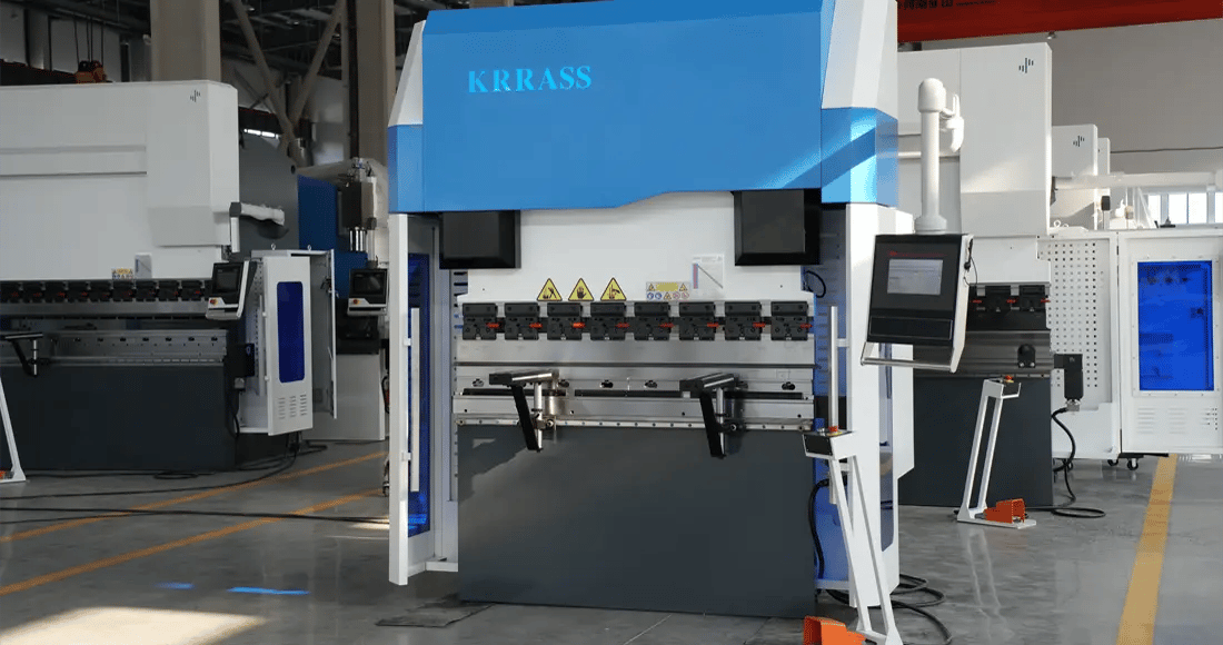
Original article image: KRRASS CNC press brake. Configuration varies by model and quotation; the photograph is not proof of a particular controller or hydraulic option.
Why the term “closed loop” must be used precisely
A machine may have a closed-loop X backgauge without having closed-loop Y1/Y2 ram control. A servo motor is only one element of a motion system; the position sensor, command path and actual controlled mechanism must also be identified. The buyer should ask the manufacturer to point out the position scales, controlled hydraulic valves, backgauge motors and crowning mechanism on the specific unit being offered.
Equally, “repeatability of an axis” does not automatically mean “accuracy of a bent part.” A scale may resolve small movements while the angle still changes because the material thickness, yield strength, punch, die and springback differ. The following sections separate controller capability from measured part quality.
Control and Machine Interfaces: What Actually Connects to What?
The control interface is one of the strongest reasons to inspect the machine before purchasing. Rather than compare only touchscreen size, examine three layers: operator interface (how a part is entered), machine-control interface (what motors, valves and sensors are commanded) and data interface (how programs, tooling libraries and other shop systems exchange information). A vendor should explain all three for the supplied configuration.

New illustrative architecture diagram. It describes functional signal paths, not an electrical wiring drawing or a controller pinout. Physical connectors, safety devices and I/O assignments must be confirmed from the model-specific manufacturer manual.
Operator-interface comparison
On many basic NC systems, the operator enters X and Y target positions, selects a bending step and adjusts a trial bend. This can be appropriate for repeated flanges and straightforward shapes. More capable controllers may store substantial multistep programs even when installed on a torsion-bar machine. The Estun E21 operation manual documents backgauge positioning, retract functions, power-off protection, and 40 stored programs with up to 25 steps each. Accordingly, the claim that NC machines have no program memory is incorrect.
Graphical CNC systems can help the operator enter bend geometry, manage tools and plan bending steps. The Delem DA-66S manufacturer specification describes 2D product programming, automatic bend sequence calculation, collision detection and 3D machine visualization. These are controller capabilities, not guarantees that every press brake fitted with the controller has all corresponding hardware options.
Control, feedback and data: practical interface matrix
| Interface | Purpose | Basic NC configuration | More sophisticated CNC configuration | Verification question |
|---|---|---|---|---|
| Controller/HMI | Enter and recall part data | Numeric fields, program steps | Numeric or graphical programming, tool library | Can you program this drawing live? |
| X-axis drive | Position backgauge front-to-back | Motor/inverter or servo depending on equipment | Usually a controlled motorized axis | What are travel, speed and tested positioning tolerances? |
| Y or Y1/Y2 feedback | Determine ram position | Depth stop or other configured feedback | Independent feedback for both ram sides where installed | Show Y1 and Y2 sensors and diagnostics |
| Hydraulic valve control | Command ram movement | Hydraulic system with machine-specific control | Proportional/servo arrangements where supplied | Identify actual valves and hydraulic drawings |
| Crowning | Compensate frame/tool deflection | Manual or optional | Manual, motorized, or programmable | Is W included and is it automatic? |
| R-axis | Raise/lower backgauge fingers | Optional on selected machines | Optional, common on better backgauges | Is R genuinely motorized and commissioned? |
| Z1/Z2 | Move individual fingers laterally | Rare or optional | Optional on more complex gauging systems | Are two independent finger drives supplied? |
| USB | Transfer or back up programs | Controller dependent | Common on graphical controllers | Can the buyer back up and restore actual programs? |
| Network/OPC UA | Shop connectivity | Often absent, may be added | Controller and option dependent | Show option license, port and export test |
| Safety I/O | Interface with safeguarding devices | Required safeguarding design | Required safeguarding design | Supply safety architecture and validation records |
This matrix is a functional comparison, not a claim about specific pin numbers. It would be unsafe and technically misleading to publish a universal pinout for E21, E310P, Delem or other controllers because OEM wiring, expansion modules, safety devices and firmware vary. Request the approved electrical drawings for the exact serial-numbered machine. Safety circuits must never be bypassed to replicate a diagram from an online article.
A controller model does not establish a complete machine configuration
Delem’s current DA-53Tx page describes graphical programming, USB exchange, crowning capability and optional connectivity. The DA-58Tx page emphasizes 2D graphical programming and bend-sequence simulation. Specific display sizes, software features and expansion interfaces differ between generations and revisions. If a machine brochure and a controller manufacturer’s currently published page disagree, rely on the exact controller part number and dated datasheet supplied for the quoted machine—not an assumed screen size from an older article.
In practice, ask for four photographs: the front of the actual HMI; the installed controller nameplate; the cabinet with identifiable drive and I/O modules; and the hydraulic/scale arrangement. Then require a demonstrated program transfer and a real part bend. Those checks are much more reliable than interpreting a promotional rendering.
CNC Press Brake vs NC Press Brake: Real KRRASS Configurations
The following table uses specific publicly described KRRASS products as examples. These are configuration references rather than a controlled factory comparison. Published product information may change. Before ordering, have the supplier confirm the full bill of materials, delivered controller, actual axes, safeguarding, clamping and service scope in a dated quotation.
| Published product | Listed force | Listed bending length | Controller and published axes | What it demonstrates |
|---|---|---|---|---|
| WC67K-80T2500 E21 NC | 800 kN | 2,500 mm | E21; Y+X | Straightforward NC configuration |
| WC67K-125T3200 E21 NC | 1,250 kN | 3,200 mm | E21; Y+X | Higher-capacity NC example |
| WC67K-200T3200 E21 NC | 2,000 kN | 3,200 mm | E21; Y+X | NC can offer substantial nominal force |
| MB8-80T2500 DA-53T CNC | 800 kN | 2,500 mm | Y1+Y2+X+R+W listed | Comparable nominal force/length, different control package |
| MB8-110T3200 DA-53T CNC 3+1 | 1,100 kN | 3,200 mm | Y1+Y2+X+W listed | One basic synchronized CNC axis arrangement |
| MB8-110T3200 DA-53T CNC 4+1 | 1,100 kN | 3,200 mm | Y1+Y2+X+R+W listed | Additional R-axis at similar force/length |
| PBS-110T2500 DA-58T CNC | 1,100 kN | 2,500 mm | Y1+Y2+X+R+W listed | Different series and graphical controller |
The presence of a 200-ton NC model in this table is intentional: NC does not mean low-tonnage. Likewise, an 80-ton CNC machine is not automatically suitable for every 80-ton job. Tool loading, working length, center and off-center limits, daylight, open height and bending method must all be checked. Model titles and “axis count” labels should be interpreted alongside the detailed technology specification.
Two published price references and their limitations
For a useful starting illustration, the WC67K-80T2500 E21 page showed a USD 11,160 reference price, while the MB8-80T2500 DA-53T page showed USD 19,599 when checked for this update (October 29, 2026). Both list 800 kN and 2,500 mm, so their nominal capacity and length are similar. The arithmetic difference is USD 8,439. This is a useful illustration of the purchase decision, not a controlled price premium attributable exclusively to NC vs CNC.
Different control systems, backgauge axes, machines, guarding, tooling, installation scope and commercial terms may be included or excluded. Published references are not guaranteed transaction prices, current stock confirmations or destination-specific landed costs. For an apples-to-apples procurement method, use the KRRASS guide to comparing CNC hydraulic press brake quotations. Ask suppliers to itemize machine, tools, loading, shipping, commissioning, training, spare parts, taxes and payment terms before comparing offers.
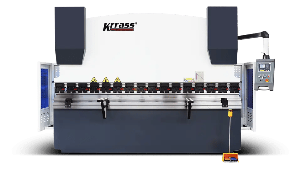
Original article image: KRRASS WC67K-series NC press brake. Check the actual controller and options against the order confirmation.
What the family pages tell us
KRRASS describes EssentialBend as a torsion-bar synchronized system and identifies backgauge combinations such as X, X+R, or X+R+Z1+Z2, depending on the equipment selected. It lists control options ranging from basic E21 to more capable alternatives. The page itself illustrates why the phrase “NC cannot have multiple axes” is too broad.
KRRASS describes StandardBend with closed-loop hydraulic control, Delem 53Tx/58Tx and other control options, and BG-2 or BG-4 arrangements. Those backgauges can be chosen according to part diversity rather than automatically specified for every buyer. The AdvancedBend family provides another product path for shops evaluating more demanding CNC forming requirements. Treat each as a configuration platform, not a promise that every catalog feature appears on every machine.
Calculating Bending Force Before Comparing Machine Types
Machine selection can fail even when the NC vs CNC discussion is technically correct. A buyer may choose the controller first, then discover that the available press brake tonnage or die opening cannot handle the actual material. Bending force should be calculated before choosing an NC or CNC model. The following examples use the same baseline as the KRRASS press brake tonnage calculator, so readers can reproduce them instead of accepting unexplained tonnage numbers.
The air-bending baseline and exactly when to use it
For an initial air-bending estimate in mild steel with an assumed ultimate tensile strength of 450 MPa, the KRRASS calculator uses:
P (kN) = 650 × S² × L / V
Here S is material thickness in mm, L is bend length in meters, V is the die opening in mm, and P is force in kN. The mixed units are part of this calibrated empirical formula; do not substitute L in millimeters or V in inches without conversion. For another assumed tensile strength, multiply the mild-steel result by UTS / 450, where UTS is in MPa. Divide kN by 9.80665 to obtain metric tons-force (t). A metric ton-force is not the same as a US short ton-force.
This approximation does not independently predict all effects of yield strength, material temper, radius, grain direction, lubrication, process dynamics or tooling geometry. It is not an approved load chart for your machine. It should not be applied unchanged to bottoming, coining, hemming or special forming. Confirm actual material properties against grade and inspection documentation; ISO 6892-1:2019 defines a test method for determining mechanical properties in room-temperature metallic tensile testing.
Worked example A: 3 mm mild steel, 2 m bend
Suppose the customer requires a 90-degree air bend in a 3 mm mild-steel sheet. The estimated UTS is 450 MPa, the bend length is 2.0 m, and a V24 die is provisionally selected. The arithmetic is:
P = 650 × 3² × 2.0 / 24 = 487.5 kN. 487.5 / 9.80665 = 49.71 metric tons-force. With a preliminary 25% allowance: 49.71 × 1.25 = 62.14 metric tons-force.
In nominal force terms, an 80-ton machine looks possible for this centered, properly supported bend. The choice between an 80-ton NC or 80-ton CNC model must therefore turn on geometry, machine loading restrictions, tools, production economics and verified bend quality—not the approximate force alone. Check die and punch ratings, machine distribution rules and the approved effective working length before authorizing production.
Worked example B: the same sheet over 3.2 m
Keep material strength, thickness and V24 die unchanged, but increase bend length to 3.2 m:
P = 650 × 3² × 3.2 / 24 = 780 kN = 79.54 metric tons-force. At 25% preliminary allowance: 99.43 metric tons-force.
An 80-ton nominal machine is no longer a sensible starting choice under that sizing convention, whether it is NC or CNC. A 110- or 125-ton class may be worth evaluating, subject to load charts and acceptable margin. This simple example demonstrates why the words “CNC has more bending strength” are wrong: the rated machine force, geometry and load condition determine capacity.
Worked example C: the stainless-steel correction
For the original 3 mm × 2 m × V24 case, assume a 650 MPa UTS for a specific stainless-steel planning scenario. Apply the correction factor 650 / 450 = 1.4444:
P = 487.5 × (650 / 450) = 704.17 kN = 71.81 metric tons-force. At 25% allowance: 89.77 metric tons-force.
This is not a measured value for every stainless-steel grade. It shows that retaining the same machine capacity while changing material can be a major error. The exact material certificate, thickness tolerance, bend radius and tool geometry must be reviewed before producing the part.
Force calculation table: same assumptions, transparent results
| Case | Material UTS used | S | L | V | Estimated P | Force (metric t) | With 25% planning allowance |
|---|---|---|---|---|---|---|---|
| A: mild-steel short bend | 450 MPa | 3 mm | 2.0 m | 24 mm | 487.5 kN | 49.71 t | 62.14 t |
| B: mild-steel full-length bend | 450 MPa | 3 mm | 3.2 m | 24 mm | 780.0 kN | 79.54 t | 99.43 t |
| C: stainless planning case | 650 MPa | 3 mm | 2.0 m | 24 mm | 704.2 kN | 71.81 t | 89.77 t |
| D: mild-steel thin sheet | 450 MPa | 2 mm | 2.5 m | 16 mm | 406.3 kN | 41.43 t | 51.78 t |
Meaning of the margin: The 20–25% sizing allowance suggested by the KRRASS calculator is a preliminary planning approach, not an instruction to apply 125% of the machine’s rated force and not a substitute for manufacturer safety limits. A buyer should separate a capacity reserve from any true load-rating limit. The acceptable reserve depends on the process and the real equipment specifications.
V opening, inside radius and minimum flange
The die opening influences more than force. The same KRRASS calculator uses air-bend planning approximations of inside radius ≈ 0.16 × V and minimum 90-degree flange ≈ 0.78 × V for its demonstrated conditions. For a V24 die, these estimates are about 3.84 mm inside radius and 18.72 mm minimum flange. Neither value is a guaranteed final dimension; confirm them against tool shoulders, material, drawing requirements and a test part.
A narrower V typically raises force and may shorten the minimum feasible flange. A wider V typically reduces force but changes bend radius and minimum flange. If the part’s flange is too short for the chosen V, buying a larger CNC machine does not fix the geometry. It is a tooling or part-design problem. Read the KRRASS press brake tooling guide for compatible punches, dies and bending-method constraints, and use the tonnage calculator to explore a realistic die opening before requesting a quotation.
CNC Press Brake vs NC Press Brake Accuracy: What to Measure
Buyers often ask which press brake is “more accurate.” The question must be divided into axis positioning, ram parallelism, angle accuracy, flange-dimension accuracy, repeatability and long-bend consistency. These are different measurements. A published backgauge positioning claim cannot be converted directly into an angular tolerance, and a controller resolution cannot establish a finished-part accuracy specification.
A bent angle is influenced by tool geometry, ram depth, material variation, springback, temperature, crowning, seating of the sheet on the die, and the operator’s process. A flange dimension additionally depends on backgauge contact, blank size, bend deduction and workpiece position. Even a premium CNC machine cannot eliminate variability in incoming sheet without measurement and compensation methods matched to the application.
Ask for a reproducible acceptance trial
A serious buyer can ask the supplier to run a defined test using a representative drawing and material sample. The test should record actual settings, not only the pass/fail result. Use a calibrated or otherwise suitable angle-measuring instrument and an appropriate dimensional measurement system. Agree on the measurement procedure and acceptance limits before the test.
- Record incoming material. Note grade, heat or batch, actual thickness at several locations, nominal UTS or material certificate information and the blank dimensions.
- Document tooling. Record punch identity and radius, die opening, tool segment arrangement, holder type, relevant load ratings and crowning settings.
- Record machine configuration. Note actual axis list, controller version, installed position scales, warm-up state and hydraulic-oil temperature where relevant.
- Bend an agreed sample. Use the same nominal geometry and an agreed number of samples on both candidate machines. Do not change geometry to favor one candidate.
- Measure repeatability. For example, measure five parts from one setup, then repeat after a controlled job change and restoration of the original settings.
- Assess long-bend behavior. If relevant, record bend angle near both ends and the middle, and compare with the drawing’s angle tolerance.
- Inspect safety and quality. Look for cracking, surface marking, tool collision risk, flange deviation and unsafe handling requirements.
- Retain test evidence. Require a signed report containing the drawing, material, measurements and settings.
| Test item | Example measurement | What it establishes | What it does not establish |
|---|---|---|---|
| Backgauge positioning | Repeated physical X-position readings | Axis position performance | Finished bend-angle accuracy |
| Five-part angle series | Angle at a defined measurement location | Short-run process consistency | All materials and bend lengths |
| Long-bend three-point reading | Left, center, right bend angles | Effect of deflection/crowning in that setup | Unrestricted eccentric loading |
| Changeover and restore | Time and first-good-part result | Setup workflow repeatability | Universal productivity gain |
| Program backup and restore | Successful return to stored parameters | Data handling and operator workflow | Cybersecurity or network compatibility |
A transparent tolerance example
Suppose a drawing requires a 90.0° ±0.5° bend, measured using a specified method. Five illustrative parts measure 89.8°, 90.1°, 90.0°, 90.2°, 89.9°. All five satisfy that angle limit, and the observed range is 0.4°. That does not justify claiming the press brake’s universal accuracy is ±0.2°, because the small sample does not cover other loads, batches, operators, temperatures or tooling. It is only evidence that this trial met the agreed criterion.
Likewise, if a machine achieves the angle but misses a ±0.2 mm flange tolerance, the problem may be blank variation, X-axis calibration, datum placement or the developed-length assumptions. A buyer must define both requirements independently. For how changes in bend radius affect flat patterns, see the KRRASS guide to bend allowance and bend deduction.
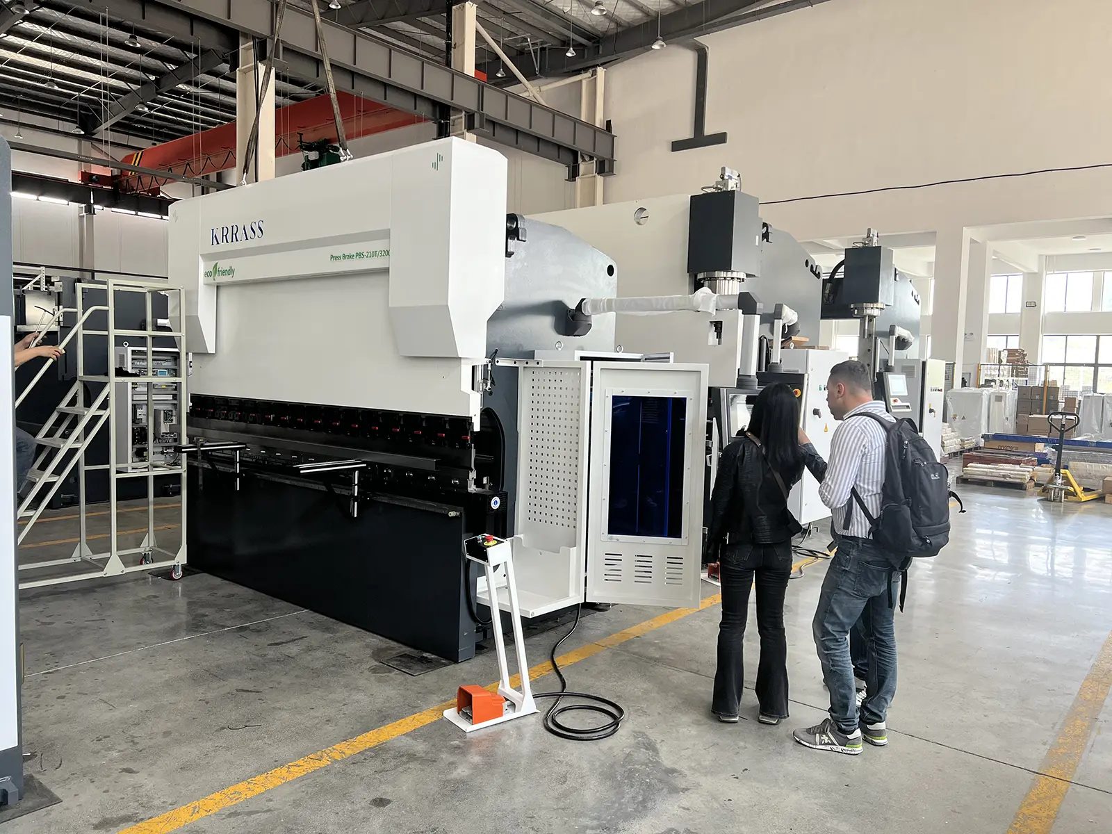
Original article image: real press brake equipment in a factory setting. A photo documents installation context but should not be presented as dimensional test evidence.
Programming and Setup: Where CNC Can Save Time—and Where It Cannot
A modern CNC workflow can include geometry entry, tool libraries, bend order, backgauge movement, graphic previews and stored corrections. For multi-bend parts, these features can reduce the time spent interpreting drawings and manually re-entering step values. A shop with repetitive simple bends may see less benefit because its NC setup is already well understood and fast. Programming capabilities should be tested against actual jobs rather than judged by the number of menu screens.
One practical setup-time comparison
Imagine a factory making an L-bracket with two repeated flange dimensions. On an NC machine, the operator recalls a short program, checks the stop position, installs the required tool and performs a trial bend. On a CNC machine, the operator recalls the stored graphical job and tool data, then checks setup and bends a test part. The CNC workflow may be no faster if there is no change of tooling and the NC program is already stable.
Now imagine a box-shaped enclosure requiring several steps, different backgauge finger positions and a gooseneck tool. The CNC machine may provide sequencing, calculated positions and clear prompts that reduce setup uncertainty. Even then, the actual benefit depends on whether the control has the correct tooling database, axis hardware and usable software. Graphic simulation cannot prevent a collision if the entered geometry or tool dimensions are wrong.
What the operator should demonstrate
Ask an operator who is familiar with the machine to start with a supplied drawing and complete the process while a buyer observes: register the tool, create or retrieve the part, check the bend sequence, position the backgauge, conduct a safe first bend, measure the angle, enter a correction, finish the part and archive the program. Record the setup time separately from active bending time and time spent waiting for support.
| Workflow element | NC consideration | CNC consideration |
|---|---|---|
| First part for a simple bracket | Direct numeric setup can be quick | Graphical setup may not add much value |
| Multi-bend enclosure | More operator planning and manual checking may be needed | Tool library and sequencing can help |
| Repeat production of the same job | Stored simple steps may work well | Stored detailed steps and corrections may help |
| Material-batch changes | Trial bend and adjustment still necessary | Corrections may be stored, automation optional |
| Operator handover | Standard setup sheets are important | Standard setup sheets and program/version control remain important |
| Different tooling | Program or stop values may need review | Tool library can recalculate, if entered correctly |
In the original article, NC was described as well suited to one-off bespoke projects. This deserves qualification. Very simple one-off parts may indeed be economical on NC equipment. But complex one-off parts can benefit disproportionately from CNC simulation because the operator may save trial pieces even though only one final part is required. The deciding factor is the complexity of the setup, not solely the batch quantity.
The Backgauge and Crowning: Two Features Buyers Commonly Under-Specify
The backgauge establishes a repeatable physical reference for the next bend. X moves the stop front-to-back; R adjusts finger height; Z1 and Z2 can reposition fingers laterally; X1/X2 and other configurations may support angled gauging when designed and installed. Not all movements are independently powered, and axis nomenclature varies. Ask for a signed drawing of the installed backgauge and demonstrate each promised movement at the machine.
A basic X-only backgauge is often sufficient for L-brackets and simple channels. R can help with parts whose geometry requires different vertical stop positions. Independent Z axes can reduce manual finger repositioning on different widths and complex parts. But unnecessary motorized axes increase cost, maintenance requirements and training burden. Their value should be justified by drawings, not by the assumption that more axes always means better quality.
Crowning is not an optional detail when long-bend consistency matters
Under load, the bed and ram deflect. Without suitable compensation, a long bend may produce different angles along its length even when the ends seem correct. Crowning changes the relative profile of the support or tooling to compensate for this behavior. Depending on the model, it can be manually adjusted, motorized or programmable. A name like “W axis” normally identifies some form of crowning control in a quoted configuration, but it does not prove that the machine will automatically calculate the ideal value in every process.
The proper acceptance test is a long, representative bend measured at several locations. Record the crowning setting and repeat after a setup change. A supplier’s general claim of “high accuracy” is weaker than a measurement sheet showing actual angles across the bend for a documented material, tool and load. See KRRASS press brake tooling guidance for the link between tool alignment, die selection and crowning.
NC vs CNC Press Brake Costs: Build the Case with Your Data
The difference between NC and CNC rarely ends with the invoice. A purchasing decision also affects setup labor, reject parts, training, maintenance, software, storage and financing. The original article discussed long-term value qualitatively; the better approach is to model it with inputs the factory can verify. Avoid a generic claim such as “CNC reduces labor by 40%.” No single percentage applies across products, operators and machines.
What should be included in total cost of ownership?
| Cost category | Suggested measurement | Caution |
|---|---|---|
| Machine and options | Supplier’s dated, itemized quote | Ensure comparable tooling and guarding |
| Freight and installation | Written delivery and commissioning scope | Incoterms and local costs can dominate |
| Operator setup labor | Minutes per changeover × annual changeovers | Avoid counting labor savings twice |
| Production labor | Actual cycle time and staffing requirement | Machines do not necessarily remove an operator |
| Scrap or rework | Documented reject units × loss per unit | Use only attributable differences |
| Maintenance | Preventive work, spares and actual callouts | New CNC may need specialized service |
| Training | Paid instruction and production ramp time | Both types require safe operator training |
| Energy | Measured kWh per accepted part | Do not infer consumption from motor nameplate alone |
| Financing and capital | Interest, depreciation, hurdle rate | Use consistent time horizon |
| Residual value | Evidence-based expected resale price | Never assume a fixed CNC resale premium |
Illustrative high-mix factory calculation
Consider ten job changes per working day, 250 operating days per year, and an observed or projected eight-minute reduction in setup time with the proposed CNC process. At a fully burdened, eligible labor rate of USD 35 per hour, the annual opportunity is:
10 × 250 × 8 / 60 = 333.33 hours per year. 333.33 × USD 35 = approximately USD 11,667 per year.
Now suppose the factory makes 60,000 parts a year and verified process trials suggest an absolute 1.5 percentage-point reduction in scrap or rework attributable to the machine and workflow. At a USD 8 loss per rejected part, the modeled reduction is:
60,000 × 0.015 × USD 8 = USD 7,200 per year.
The combined modeled benefit would be USD 18,867 per year. If the CNC system costs USD 24,000 more fully installed and requires USD 2,500 more annual support costs, the modeled net benefit becomes USD 16,367 per year, implying a simple undiscounted premium payback of approximately 1.47 years. This is a scenario, not measured KRRASS equipment performance. The claimed scrap reduction must be proven; if it is zero, the case changes materially. Also, time saved is not a cash saving unless it reduces paid hours, increases saleable capacity or avoids other cost.
Illustrative low-mix factory calculation
Now consider a shop with only three job changes a day, 220 days per year, and a possible three-minute setup-time reduction. The same USD 35 hourly rate yields:
3 × 220 × 3 / 60 = 33 hours per year, worth USD 1,155 per year if the time is economically recoverable.
Suppose a documented trial justifies only 0.3 percentage points of waste improvement on 20,000 parts, at USD 6 per rejected part. That equals 20,000 × 0.003 × 6 = USD 360 per year. Together, these modeled gains total USD 1,515, before any extra maintenance or software expense. In this situation, a significantly cheaper NC machine that passes all quality and safety tests may deliver a better financial return.
Break-even formula, sensitivity and hidden assumptions
An elementary annual net-benefit model is:
Annual net benefit = (annual setup hours recovered × economic hourly value) + verified scrap/rework savings + other evidenced savings − incremental annual operating costs.
Simple payback (years) = installed CNC price premium / positive annual net benefit.
If the annual benefit is zero or negative, the simple payback is undefined—not zero years. For a full investment analysis, account for financing, tax effects, residual value, replacement schedules and the company’s discount rate. A purchasing manager may prefer the net present value (NPV) of documented cash flows over an attractive but fragile payback estimate.
| Sensitivity: high-mix scenario | Assumed annual net benefit after USD 2,500 support cost | Payback on USD 24,000 premium |
|---|---|---|
| Setup labor benefit only | USD 9,167 | 2.62 years |
| Setup plus half the modeled waste saving | USD 12,767 | 1.88 years |
| Setup plus full modeled waste saving | USD 16,367 | 1.47 years |
| Half the modeled setup benefit, no waste savings | USD 3,333 | 7.20 years |
The table makes uncertainty visible. A serious factory should replace every assumption with its own cycle sheets, reject reports, labor costing and final supplier offers. This is a more credible approach than quoting an industry-wide return on investment percentage without independent data.
Comparing Energy Consumption Without Misusing the Motor Rating
A CNC press brake may use a conventional hydraulic pump, a hybrid servo pump or another drive technology. An NC machine may likewise differ in motor and pump design. Therefore, neither “NC always uses less energy” nor “CNC always uses less energy” is defensible. Machine family, motor control, idle time and duty cycle matter more than a simple controller label.
To compare energy, measure kWh per accepted part for a representative workload. Record idle consumption, actual running energy and good units produced, using comparable workpiece size, material, tooling, guarding and labor conditions. Power in kW is an instantaneous or rated measure; energy in kWh accumulates over time. A 7.5 kW nameplate does not prove the machine consumes 7.5 kWh every hour, nor that two 7.5 kW machines consume equal energy during intermittent bending.
A fair test should include startup, waiting for material, backgauge movement, the productive bending cycle and realistic intervals between orders. If a hybrid hydraulic system offers lower idle consumption, the potential annual saving depends heavily on how often the machine waits rather than bends. The StandardBend machine family lists servo and conventional AC motor power-source approaches, illustrating why energy comparison must be made at the specified drive level.
Safety: NC and CNC Both Require a Machine-Specific Risk Assessment
Safety should never be presented as a bonus feature reserved for higher-priced CNC equipment. A power press brake creates hazards around the punch and die, moving sheet, backgauge, side and rear access, tooling changes, stored hydraulic energy and unexpected cycling. The safeguarding arrangement must be appropriate to the actual machine, operator tasks and jurisdiction. A touch screen or an emergency-stop button by itself is not a complete safety system.
The US Occupational Safety and Health Administration provides a powered press brake machine-guarding overview and the general machine-guarding requirements in 29 CFR 1910.212. The ANSI B11 standards list identifies ANSI B11.3-2022 as the current power-press-brake-specific safety standard. These references establish a safety framework, not a blanket certification for any particular model.
A buyer should request a written description of the point-of-operation safeguarding, side and rear guarding, stop and restart behavior, foot control protections, safety-rated interfaces, risk assessment and the practical validation procedure. The correct approach can differ depending on hand-fed workpieces, long panels, robots or special tooling. If sensors are supplied, verify that they are integrated into the actual safety architecture instead of treated as decorative add-ons.
Maintenance and repair also create stored-energy risks. The OSHA lockout/tagout rule, 29 CFR 1910.147, addresses hazardous energy during covered service activities. Technicians must follow the actual machine’s approved isolation and stored-energy procedures. An article cannot replace them, and the illustrative controller diagram above must not be used to wire or defeat a safety circuit.
The safety checklist for a machine demonstration
| Check | What the buyer should witness |
|---|---|
| Point-of-operation protection | Correct safeguard response to the planned bending task |
| Foot control | Protected against unintentional activation where required |
| Emergency stop | Appropriate stopping and reset behavior under approved test procedures |
| Side/rear access | Suitable protection against access to dangerous movement |
| Tool changes | Safe clamping, tool handling and documented setup method |
| Long workpieces | Plan for part movement, lifting aids and pinch/crush hazards |
| Service | Documented isolation of electrical, hydraulic and stored energy |
| Records | Applicable conformity documentation, risk assessment and training materials |
A supplier’s statement that a machine is “CE compatible” or “equipped with a laser safety device” does not substitute for evaluating the delivered installation and its documentation. Regulations differ by country; require the legal and standard-specific compliance evidence relevant to the machine’s destination.
NC vs CNC Press Brake Demonstration and Acceptance Testing
A convincing evaluation should reduce subjective factors. Prepare three representative drawings: one simple repeated bracket, one complex multi-bend part and one long bend that stresses the available working length. Where relevant, add a fourth part with an approved, controlled off-center loading case. Do not assume the NC design is permitted to perform that last test; get manufacturer approval first.
Ask both suppliers to identify their exact machine and tooling configuration. Use equivalent material from the same batch when possible, measure blank thickness, record the installed die and punch, establish tolerances, and decide what counts as a first acceptable part. An operator should be permitted ordinary setup and safety checks; forcing a rushed setup is neither fair nor safe.
Suggested comparison scorecard
| Category | Weight (illustrative) | What to score |
|---|---|---|
| Part feasibility and available capacity | Pass/fail | Material, force, tool capacity, clearance, length |
| Safety and required documentation | Pass/fail | Guarding and destination-specific requirements |
| Angle and flange results | 25% | Test data against agreed drawing limits |
| Setup and changeover | 20% | Minutes to first accepted part, across two jobs |
| Long-bend consistency | 15% | Left/center/right angle variation |
| Operator usability and program recovery | 10% | Independent operator demo, backup and restore |
| Maintainability and support | 15% | Access, documentation, spares and service terms |
| Five-year ownership economics | 15% | Comparable installed price and evidence-based costs |
How to apply the scorecard: Capacity and safety are gate requirements, not weighted preferences. A machine that cannot safely produce the part should be rejected even if its quoted price is attractive. For machines that pass, assign a consistent 0–5 rating to the remaining criteria, multiply by their stated weights and document the reasons. The weights above are an example: adjust them to the shop’s actual constraints before opening the commercial bids.
When reviewing machine demonstrations, record at least the first-good-part time, total good units produced, the number of trial blanks, dimensional inspection results, actual interruptions, operator interventions and any unplanned special tooling. A supplier’s video may be helpful context but it cannot replace a witnessed or independently documented acceptance test where the risk and investment warrant one.
Tooling, Flat Patterns and Material Variability: Shared Constraints of Both Machine Types
Neither NC nor CNC can overcome an incompatible V opening, wrong tooling tang, insufficient open height or impossible bend geometry. A press brake may meet a force specification and still be incapable of producing a cabinet if the punch collides with a return flange. Therefore, tooling, gauge positions and collision clearance should be reviewed at the same time as the main machine selection.
Material variability also affects bending angles and developed length. The bend allowance, bend deduction, inside radius, K-factor and springback relate to the actual process rather than the prestige of a controller. A CNC control may help manage corrections and tool libraries, but the calculation assumptions must still be validated by test bends. The detailed formulas belong in the dedicated bend deduction versus bend allowance guide; repeating an entire flat-pattern tutorial here would distract from this equipment comparison.
For buyers, the practical requirement is to provide representative drawings and ask whether the quoted press brake, tools and software can perform those bends without collisions. Request a tool list, including style, section lengths, die openings, punch heights and load ratings. A “standard tooling included” line without these details is not a meaningful guarantee of compatibility.
The risk is greatest when buying a machine from a supplier whose clamp format differs from the tools already owned by the factory. Adapters may be possible but can change available height, load capacity or alignment. Confirm integration details and tool files before placing an order. CNC digital tooling libraries are most helpful when their geometry matches the actual installed hardware.
Maintenance, Training and Service: Build a Realistic Plan
The original article emphasized daily, periodic and annual maintenance. That concept remains useful, but the exact service interval should come from the supplied machine manual, its duty conditions, hydraulic system and local maintenance plan. “Change all hydraulic oil quarterly” is not a universal best practice; intervals depend on oil condition, filtration, duty cycle and the manufacturer’s recommendations.
For an NC torsion-bar machine, inspection may emphasize mechanical synchronization linkages, stops, backgauge drive, hydraulic leaks and machine/tool alignment. For a closed-loop CNC system, additional attention may be required for linear scales, cabling, proportional hydraulic valves, axis reference procedures and controller data. Both types require safe guarding inspection, hydraulic system health, clean tooling and trained operators.
Suggested responsibility matrix—not a replacement for the manual
| Frequency or trigger | Example checks | Responsible person |
|---|---|---|
| Before each shift | Guarding, tool seating, visible leaks, stop function, unusual sounds | Trained operator under local procedure |
| After a material or tool change | First-part dimensions, angle, program/tool consistency | Operator and quality personnel |
| Periodically per OEM plan | Lubrication, backlash or alignment, filtration, coolant/oil condition as applicable | Qualified maintenance team |
| After control or hydraulic service | Reference/calibration, limit verification, suitable controlled test bends | Qualified technician |
| After a significant collision | Tool damage, machine alignment, safety protection and cause review | Maintenance, production and safety team |
| At the defined acceptance/qualification interval | Repeatability and dimensional process capability | Quality and engineering team |
Training should focus on practical ability: reading drawings, selecting tooling, calculating tonnage, recognizing collisions, using the backgauge, recording corrections and safeguarding the operator. A sophisticated graphical controller can help beginners navigate complex jobs, but it does not make operator competence unnecessary. An NC machine may be easier to learn for limited tasks but can demand more experience when geometry and process variation become difficult.
For equipment support, ask about language availability, electrical/hydraulic documentation, authorized access to parameter backups, remote diagnosis, local spares, training scope and realistic service response. KRRASS provides an overview of its after-sales service and details should be made contractual for each purchase. Do not rely only on a verbal guarantee.
Future Expansion: Choose the Interfaces You Will Actually Use
Digital manufacturing is relevant to modern press brakes, but it should be evaluated as a real requirement rather than an abstract Industry 4.0 promise. Ask whether the specific controller and software license can exchange program data with the shop’s CAD/CAM system, whether approved network access is available, and what data can actually be exported. USB backup and Ethernet connectivity are different capabilities. A machine connected to the network is not necessarily producing valid part-level production records.
For example, the Delem DA-53Tx manufacturer specification lists USB and optional networking/OPC UA-related capabilities in its product information. The DA-66S page identifies further programming and optional sensor integrations. These descriptions provide a basis for questions, but they do not prove a specific machine has a purchased connectivity license or a completed ERP integration.
If a factory expects to use offline programming, confirm the exact software version, licensing method, compatible file formats and supported tool libraries with its controller supplier. Ask to open a real drawing, transfer a job, restore it after a backup and produce a valid part. Offline software should not be assumed to be free, unrestricted or interchangeable between computer generations.
A purchase decision should also consider whether future requirements would be better addressed by different technology entirely. Small high-mix parts may justify a servo-electric machine; flexible panel-production lines may require a panel bender. The comparison remains NC versus CNC for this article, but a buyer is better served when all realistic forming options are considered.
CNC Press Brake vs NC Press Brake: Six Buyer Scenarios
Scenario 1: A small shop with stable brackets and channels. If most jobs use the same material and simple angles, the changeover count is low, operators are experienced and an NC machine passes all safety and dimensional tests, an NC torsion-bar design may offer the best capital efficiency. Budget for appropriate tooling, commissioning and training rather than spending the entire budget on nominal tonnage.
Scenario 2: A fabrication job shop with many short orders. When daily changeovers, drawing variety and first-part approval consume significant labor, a CNC machine with a well-supported controller, accurate tool library and suitable backgauge becomes attractive. Verify the savings using observed setup time and waste reports; do not assume automation necessarily reduces headcount.
Scenario 3: A factory making long visible panels. Consistent angle across a long bend, cosmetic finish and reliable support matter more than screen size. Compare actual crowning behavior, tool condition, flatness and test bends. A CNC machine with well-managed compensation may be appropriate, but even a premium controller will not compensate for incompatible tools or poor process control.
Scenario 4: A heavy-fabrication workshop. Begin with force, bend length, tooling rating, load position, daylight and machine construction. A high-tonnage NC machine may work well for simple repetitive plate bends. For demanding sequences or controlled uneven loads, evaluate a CNC synchronized design with written manufacturer approval of those loads. Never substitute controller sophistication for load capacity.
Scenario 5: A cabinet manufacturer growing from one shift to two. Documentation, job repeatability, program backups and operator handover become more important as more personnel share the same machine. CNC features may reduce variation between setups, but standardized NC setup sheets can also work for simple parts. Compare the training and quality-control burden under the planned staffing model.
Scenario 6: A factory planning CAD/CAM or connected production. Confirm the software and interface architecture early. A network-ready controller, approved data export, tool library, documented licenses and the right backgauge may be prerequisites. A cheap machine requiring extensive retrofit later may have a higher lifecycle cost. Conversely, an advanced package whose features are never activated creates avoidable capital expense.
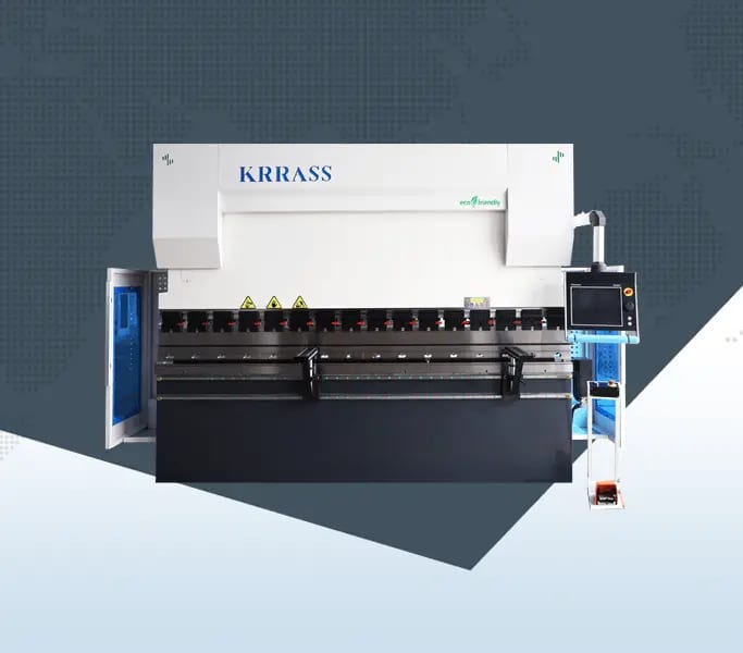
Original article image: KRRASS CNC press brake. Use product and controller identification from the exact quotation, not from the generic filename of the original image.
The Buying Checklist: 25 Questions to Send With Your RFQ
Before asking which machine is cheaper, send a consistent request for quotation. This makes competing quotes easier to compare and exposes missing options before they turn into installation disputes.
| # | Question for the supplier | Evidence requested |
|---|---|---|
| 1 | What is the exact machine model? | Nameplate and model drawing |
| 2 | What is rated force in kN? | Technical sheet and load chart |
| 3 | What is usable bending length? | Rated working-length specification |
| 4 | What is the ram synchronization system? | Mechanical/hydraulic design description |
| 5 | Are Y1 and Y2 independently measured and controlled? | Scale and control-system documents |
| 6 | What is the exact controller model and revision? | Nameplate and current datasheet |
| 7 | Which axes are installed? | Axis list and physical demonstration |
| 8 | Is crowning manual, motorized or programmable? | Device model and test results |
| 9 | What is the X travel and speed? | Specification and demonstration |
| 10 | Are R, Z1 and Z2 included or optional? | Itemized option schedule |
| 11 | What are the daylight, stroke and open height? | Dimension drawing |
| 12 | Which punches and dies are supplied? | Itemized tooling schedule |
| 13 | What is the tooling clamp standard? | Clamping-system drawing |
| 14 | What are the tool load ratings? | Tool specifications |
| 15 | Are the proposed parts free from tool collisions? | Trial or validated simulation |
| 16 | Which materials and thicknesses were calculated? | Tonnage worksheets |
| 17 | What off-center loading is permissible? | OEM load limits in writing |
| 18 | What are the agreed angle and flange acceptance criteria? | Signed acceptance procedure |
| 19 | Which operator protection systems are supplied? | Safety design and documentation |
| 20 | What is the electrical supply specification? | Nameplate and installation requirements |
| 21 | Are USB, networking and offline software included? | Licenses and functional demonstration |
| 22 | How are programs backed up and restored? | Demo and user instructions |
| 23 | What installation and training are included? | Commissioning and training scope |
| 24 | What are warranty exclusions and service response terms? | Written service agreement |
| 25 | What is the complete delivered and installed price? | Itemized quotation and trade terms |
For guidance on the wider purchase process, see the KRRASS press brake product range, the NC press brake collection, and the CNC hydraulic press brake price and quotation guide. The right equipment should be chosen from the workpieces and documented performance envelope, not the highest advertised axis count.
NC vs CNC Press Brake: Frequently Asked Questions
Is an NC press brake the same as a manual press brake?
No. NC means numerical control, and common NC hydraulic press brakes have electronically controlled settings, programmable movements and a powered backgauge. Manual press brakes and hand-operated devices form a different equipment category. A basic NC controller can still store jobs and execute programmed steps; it simply may not offer the same advanced control architecture or software as a more sophisticated CNC press brake.
Does a CNC press brake always have two independent Y axes?
No. That arrangement is typical of many electro-hydraulically synchronized CNC press brakes, but the market uses “CNC” in different ways. Some torsion-bar machines have advanced CNC-style controllers and motorized gauging. Check whether independent Y1/Y2 linear scales and closed-loop hydraulic control are physically installed. The actual synchronization and feedback design matter more than the marketing name.
Is a CNC press brake more accurate than an NC press brake?
A well-configured closed-loop CNC machine often offers greater control flexibility, and may achieve better results on demanding jobs. But no universal angle or flange tolerance can be guaranteed from the label alone. Accuracy depends on the machine condition, tool setup, material and measurement method. Ask the supplier to demonstrate repeatability on your actual parts and to report the acceptance data.
Can NC press brakes store programs?
Yes. The E21 operation manual, for example, describes 40 programs with 25 steps each. The amount of storage and type of programming vary between controllers. A basic NC system may be perfectly adequate for frequently repeated, relatively simple bends. The buyer should distinguish program quantity from useful functions such as collision visualization and automatic sequence calculation.
Can an NC press brake use an R-axis backgauge?
Some torsion-bar systems offer extra backgauge axes or controller upgrades. Their availability depends on the machine design and actual configuration. KRRASS’s EssentialBend family describes several backgauge options, including X+R and X+R+Z1+Z2. Do not assume an R axis is included merely because the controller supports it; verify the physical installed movement and quote.
Can a CNC press brake bend thicker metal than an NC press brake?
Not because it is CNC. Thickness capacity comes from the actual force required for a given material, bend length, die opening and bending method, combined with the machine and tool ratings. A 200-ton NC model can have substantially more nominal force than an 80-ton CNC model. The KRRASS calculator can provide a preliminary air-bending estimate under clearly stated assumptions.
Which is better for small-batch fabrication?
It depends on the kind of small batch. Repeated simple brackets may favor NC. One-off but geometrically complex enclosures may favor CNC because graphical planning and a reliable tooling library can reduce setup trial work. Count the number and difficulty of changes, not just units produced. Evaluate both using the same drawing and timing procedure.
What does 3+1 or 4+1 axis mean on a press brake?
The notation is vendor-specific and must be explained. A listed configuration may use Y1, Y2 and X as three controlled positioning axes and describe W crowning separately; another may add R for four positioning axes plus W. Never compare two quotes from the axis-count headline alone. Request the literal installed axis list and confirm how crowning, optional fingers and hydraulic control are counted.
Do I need automatic crowning?
It can be valuable for long bends and frequently changing loads, but the need depends on the parts and acceptance results. Some jobs can be produced with a suitable manual crowning arrangement and documented settings. A machine’s nominal tonnage, long worktable or “CNC” label does not prove that automatic crowning is included. Ask for a controlled long-bend demonstration.
Is a CNC press brake safer than an NC machine?
Neither classification automatically determines safety. Both need appropriate machine-specific safeguarding, training, tool handling and maintenance practices. More advanced systems can provide useful diagnostics or integrations but should not be treated as a replacement for safeguarding. Ask for evidence relevant to ANSI B11.3, applicable local regulations and the actual risk assessment of the delivered equipment.
Is an expensive CNC controller worthwhile on a basic torsion-bar machine?
It can improve the operator interface and program handling, but it cannot by itself create independently synchronized ram motion if the mechanical and hydraulic architecture remains unchanged. Decide whether the added programming capability solves a real bottleneck. If the requirement is long-bend angle consistency or independently controlled Y1/Y2, evaluate the machine architecture rather than paying only for a touchscreen upgrade.
What proof should a manufacturer provide before I buy?
At minimum, request the exact specification and axis list, force calculation for representative jobs, approved loading restrictions, safety documentation, tooling details, agreed acceptance tolerances, and a functional demonstration. For a major investment, seek a witnessed or well-documented factory acceptance test and written commissioning scope. A product video or general accuracy claim is not a substitute for measurable acceptance results.
Final Recommendation: Select the Machine Around the Part and the Production System
The most useful conclusion in the NC vs CNC press brake discussion is that the correct choice depends on a defined operating case. NC torsion-bar equipment remains a valid solution for straightforward work, particularly when the tool package, bending load, geometry and acceptance test are satisfactory. More advanced electro-hydraulic CNC systems can make a strong case in high-mix work and demanding processes where independent control, better tooling data, additional axes and repeatable changeovers create measurable value.
For a credible decision, start with the part drawing and material, calculate force using a defined method, check the exact machine and tooling capacity, review controller and safety interfaces, then test both machines against the same quality and time requirements. Only after those conditions are met should price and ownership cost determine the winner. Machine names and generic marketing percentages should never replace evidence.
Explore KRRASS’s NC press brake models, EssentialBend, StandardBend, AdvancedBend and the broader press brake range. When requesting a configuration recommendation, send your representative drawings, grades, thicknesses, maximum bend lengths, desired tolerances, annual quantities, shift pattern and current setup bottlenecks. That information makes it possible to propose a machine and tooling package that supports real production rather than merely winning a specification-sheet comparison.
Editorial and technical note (October 29, 2026): The numerical force cases reproduce KRRASS’s published preliminary air-bending formula. Price references are publicly displayed examples, not binding quotations. Cost/ROI tables are explicitly illustrative models; no comparative factory trial is claimed. Controller-feature references describe the manufacturer product family, not guaranteed options on every installed press brake. The original site’s photographs are retained without alteration. All new interface diagrams are functional illustrations and must not be used for electrical installation or safety wiring. Final machine procurement should be based on a dated, serial/configuration-specific quotation, appropriate safety documentation and a mutually agreed acceptance test.
Share