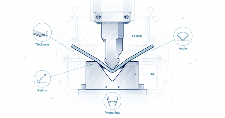
Press brake tooling is more than a set of interchangeable punches and dies. It is the physical connection between a machine’s available force and the geometry, accuracy, finish, and safety of a finished sheet metal part. A strong CNC press brake cannot compensate for a punch that collides with a return flange, a lower die with the wrong V opening, or a tool shank that does not seat correctly in the clamp.
For fabricators purchasing press brake dies, comparing American style press brake tooling with European press brake tooling, or planning a multi-machine tool inventory, the best selection is based on the actual part and machine configuration—not on a product photograph or a nominal tonnage rating. This updated guide keeps the existing practical punch-and-die selection approach while adding worked force calculations, a mounting-interface comparison, clamping and loading checks, documented machine configuration examples, and a procurement checklist that engineers can use.
Quick answer: Start with the material grade, actual thickness, bend length, angle, desired inside radius, shortest flange, and part shape. Select an air-bending V opening as a preliminary estimate, calculate bending force, check that both the machine and the exact tool segments can safely carry that load, and verify the mounting interface using measured drawings. Only then finalize the punch profile and perform a controlled test bend. For many conventional mild-steel air bends, V = 6–8 × sheet thickness is a useful first-pass range; it is not a universal specification.
Engineering scope. The examples here are transparent screening calculations, not certified load approvals or guaranteed production results. The tonnage model is aligned with the KRRASS Press Brake Tonnage Calculator. Typical radii, minimum flanges, and material strengths are assumptions stated beside each example. Verify the latest machine manual, tool manufacturer’s rated load, exact clamping drawing, actual material certificate, and site-specific safeguarding before use.

What Press Brake Tooling Does—and What It Cannot Fix
A press brake punch is the upper tool that pushes material toward a die; the die supports the material and provides a V opening or other forming profile. The upper clamp, lower holder, crowning table, and ram together establish the mechanical path through which bending force reaches the workpiece. In ordinary air bending, the sheet initially contacts the punch nose and two die shoulders. The final bend angle depends on punch penetration, material springback, and a combination of geometrical and material variables.
The existing KRRASS tooling overview already explains straight punches, gooseneck punches, segmented tooling, single-V and multi-V dies, and special tools. The more important purchasing lesson is that a geometrically suitable tool is not automatically a mechanically compatible tool. A punch can have exactly the right tip angle yet be unsafe because its tang is incompatible, its maximum load is insufficient, or its height creates a collision when the ram approaches the work.
| Decision | What to verify | Evidence to request |
|---|---|---|
| Forming geometry | Bend angle, punch nose radius, internal radius, V opening, shortest flange | Part drawing and proposed punch/die cross-sections |
| Material | Grade, temper, thickness tolerance, rolling direction, coating | Mill certificate, drawing notes, trial coupon |
| Capacity | Force per unit length and total force; short-tool restrictions | Calculations, machine chart, tool’s kN/m rating |
| Interface | Tang width, grooves, safety-retention feature, clamp jaw, die base | Dimensioned mounting drawings and sample fit test |
| Operating envelope | Tool height, ram stroke, daylight, backgauge, part rotation | Machine configuration sheet and collision simulation |
| Quality | Angle tolerance, straightness, surface marking, dimensional stability | First-article inspection and measurement records |
| Production economics | Changeovers, tool availability, segment layout, replacement cost | Tool inventory, setup-time record, batch volumes |
A tool mismatch is not always obvious on the first part. The operator may achieve one acceptable bend by changing depth or shimming a holder, while another batch fails when the material grade changes. The objective of a documented tool-selection process is repeatability across operators, shifts, and future replacement purchases.
Select the Bending Method Before Selecting the Punch and Die
For mixed sheet-metal production, air bending is normally the first method to investigate because a single set of properly chosen tools can form several open angles by changing penetration. Bottoming uses greater contact with the die geometry and generally requires more force. Coining applies substantially greater force and should never be substituted for air bending without a separate load assessment.
| Method | Main control of result | Initial tooling implication | Force-screening caution |
|---|---|---|---|
| Air bending | Punch depth, V opening, material springback | Flexible punch/die combinations | Use the air-bending calculation below |
| Bottoming | Die and punch geometry plus pressure | Closer tool-to-part matching | KRRASS calculator shows roughly 3–5 times the air-bending estimate as an initial range |
| Coining | High localized compression | Dedicated and highly rated tools | KRRASS calculator shows roughly 5–10 times the air-bending estimate as an initial range |
| Hemming | Pre-bend followed by flattening | Hemming or staged tooling | Requires a separate process and tool-loading review |
| Large-radius forming | Multiple steps or radius-forming profile | Radius punches or specialized tools | A single air-bending V formula may not represent the process |
Do not interpret the multipliers as permissible machine settings. Actual bottoming and coining load depends on tool geometry, contact, material, and the operation. The KRRASS tonnage calculation guide covers force selection in greater depth. For special bending processes, obtain an application-specific load estimate from the tooling supplier.
Material springback is especially important when the requested final angle is 90 degrees. The punch may have an included angle of 88 degrees or less to permit overbending, but this does not mean every 88-degree punch will produce a 90-degree finished part. The operator must establish the correct depth and compensation for that material and thickness. The steel producer SSAB’s bending questions and guidance highlights the interacting roles of material properties, die opening, punch radius, temperature, and friction.
V-Die Opening: Connect Thickness, Radius, Force, and Minimum Flange
The die opening, usually written as V, affects nearly every downstream decision. Smaller openings tend to increase bending force and reduce the room available for material movement. Wider openings generally reduce required force but produce a larger natural inside radius and demand a longer flange. Neither extreme is always desirable.
A quick starting table for conventional air bending is useful, provided its assumptions remain visible. The openings below are planning examples for relatively ordinary steel work—not official die requirements for every material and temper.
| Nominal sheet thickness S | 6 × S opening | 8 × S opening | Initial question before choosing |
|---|---|---|---|
| 1.0 mm | 6 mm | 8 mm | Is the flange too short for 8 mm? |
| 1.5 mm | 9 mm | 12 mm | Is the part cosmetic or coated? |
| 2.0 mm | 12 mm | 16 mm | Does the drawing accept the resulting inside radius? |
| 2.5 mm | 15 mm | 20 mm | Is a standard V size actually available? |
| 3.0 mm | 18 mm | 24 mm | Is there sufficient machine and tool capacity? |
| 4.0 mm | 24 mm | 32 mm | Will the minimum flange fit across the shoulders? |
| 6.0 mm | 36 mm | 48 mm | What is the required force across the full bend? |
| 8.0 mm | 48 mm | 64 mm | Is heavy-duty tooling and support required? |
| 10.0 mm | 60 mm | 80 mm | Have grade, bendability, and off-center loads been reviewed? |
For a conventional mild-steel air bend, an early inside-radius estimate is Ri ≈ 0.16 × V. It represents a common empirical relationship, not a promise that the part will conform to a punch tip or that every material follows the same factor. The actual formed radius can be affected by material strength, thickness, springback, punch radius, and tool condition. In particular, a large punch nose can impose a different contact geometry from the simple natural-radius approximation.

A Reproducible V-Opening Comparison for 3 mm Mild Steel
Assume a 3.0 mm sheet of mild steel with nominal ultimate tensile strength (UTS) 450 MPa, a straight 1,000 mm bend, air bending, and no additional forming features. Compare V = 18 mm, 24 mm, and 30 mm. For consistency, use the KRRASS force formula introduced in the next section, rather than mixing different empirical tonnage charts.
| V opening | V / S | Estimated force over 1 m | Natural inside radius at 0.16 V | Initial minimum flange at 0.78 V |
|---|---|---|---|---|
| 18 mm | 6× | 325.0 kN / 33.14 metric tf | 2.88 mm | 14.04 mm |
| 24 mm | 8× | 243.75 kN / 24.86 metric tf | 3.84 mm | 18.72 mm |
| 30 mm | 10× | 195.0 kN / 19.88 metric tf | 4.80 mm | 23.40 mm |
The comparison reveals the practical trade-off. Moving from V = 18 mm to 24 mm reduces modeled force by 25%, but increases the natural-radius estimate and the preliminary minimum flange. Moving to V = 30 mm reduces force further, but may make a short tab impossible to support properly. A designer asking only for “the lowest tonnage” can choose the wrong die for the actual part.
Also distinguish a nominal V dimension from the die’s complete geometry. Two tools labeled V24 can have different shoulder radii, included angles, support heights, and mounting bases. These details can affect support and surface quality even when the opening width is identical.
Calculate Press Brake Tooling Force with Stated Conditions
To make the examples consistent with KRRASS’s own software, this guide uses the baseline model published by the KRRASS online tonnage calculator:
P (kN) = 650 × S² × L / V × (UTS / 450)
Here S is actual sheet thickness in millimeters, L is the straight bend length in meters, V is the die opening in millimeters, and UTS is the assumed material ultimate tensile strength in MPa. 650 is the calculator’s empirical coefficient for the 450 MPa mild-steel baseline. The calculation is an estimate for air bending, not a universal law for every die and material.
For conversions, metric tonnes-force (tf) = kN / 9.80665. A US short ton-force is different from a metric tonne-force; the two units must not be silently interchanged. When quoting a tool in kN/m, compare it with force divided by the actual bend length in meters, and always check any separate minimum engaged length, concentrated-load, and off-center restrictions.

Worked Example: 2 mm Mild Steel, 1.25 m Bend, V16
Assumptions: 2.0 mm material thickness; 1.25 m bend length; V = 16 mm; mild steel nominal UTS = 450 MPa; air bending; straight bend; no special offsets or flange features. First calculate the baseline force:
P = 650 × (2.0)² × 1.25 / 16 × (450 / 450) = 203.125 kN.
This is approximately 20.71 metric tf for the complete 1.25 m bend, or 162.5 kN/m. The corresponding natural inside-radius estimate is 0.16 × 16 = 2.56 mm. The first-pass minimum flange is 0.78 × 16 = 12.48 mm, subject to the tool’s actual support geometry.
The calculator recommends an initial 20–25% machine-sizing margin, so applying 25% here gives 203.125 × 1.25 = 253.91 kN, or 25.89 metric tf. This margin is for selecting capacity, not a license to exceed a tool rating. A tool rated at, for example, 150 kN/m would be unsuitable under the modeled 162.5 kN/m production force even if the machine had ample total tonnage. Request the supplier’s actual tool-rating document; this 150 kN/m value is an illustrative comparison, not a published specification for a KRRASS tool.
Worked Example: 3 mm Stainless Steel, 2.0 m Bend, V24
Assume nominal UTS = 650 MPa for an illustrative stainless-steel calculation; actual grade, cold work, temper, and certification can change the figure. With S = 3 mm, L = 2.0 m and V = 24 mm:
P = 650 × 3² × 2 / 24 × (650 / 450) = 704.17 kN.
The total is approximately 71.80 metric tf, equivalent to 352.08 kN/m. A 25% initial capacity margin would produce a machine screening value near 880.21 kN, or 89.76 metric tf. The estimated radius of 0.16 × 24 = 3.84 mm is a mild-steel-style planning relationship; do not substitute it for actual stainless-steel trial measurements. The nominal 18.72 mm flange screening figure likewise must be checked against the real tool drawing.
If the selected punch is not rated for 352.08 kN/m, choose a properly rated tool or revise the method. Do not assume that installing the tool in a 160-ton machine makes the tool safe. The weakest permissible loading limit in the entire system controls the setup.
Worked Example: Why a Narrower V May Be an Expensive Solution
Consider 4 mm, 450 MPa mild steel bent over 2.5 m. On V32, the result is 812.5 kN, about 82.85 metric tf, with a 25% machine-capacity screening target of 1,015.63 kN. On V24, it rises to 1,083.33 kN, approximately 110.47 metric tf, with a 25% screening target of 1,354.17 kN. This is a one-third increase in the modeled force simply because V changes from 32 to 24 mm.
Why might an engineer still choose V24? A tighter flange or radius requirement could make V32 unsuitable. The correct decision balances geometry with actual available load capacity, not just arithmetic. If V24 cannot be supported safely, the part may need a revised flange, a larger bend radius, another forming method, or a different machine and tool set.
What the Calculation Does Not Include
The baseline equation does not certify local punch stress, a segment’s allowable concentrated load, material fracture resistance, deep box interference, or clamping security. It does not replace a tool manufacturer’s coining data, dynamic handling assessment, or recommendations for nonstandard sections. It assumes a relatively straightforward air bend; high-strength alloys may require additional consideration of bendability and tooling geometry beyond UTS alone.
For a critical order, record the material certificate, thickness measurements, actual V, bend length, estimated force, tool ratings, operator, setup number, and measured trial result. The evidence trail matters as much as the mathematical result.
Minimum Flange Length: Confirm More Than a Percentage
A short flange must remain supported by the die shoulders while the punch advances. If it cannot span the contact area reliably, the material may tip, slip, or be drawn into the opening. A smaller die opening can help a short flange, but it increases calculated force and may change the inside radius. Tool profile, shoulder radius, material thickness, bend angle, and handling method all influence the real limit.
The older article uses 70% of V as a broad rule of thumb; the current KRRASS calculator uses 78% of V for its 90-degree air-bend screening value. These are not interchangeable precision limits. For consistency with the current calculator, the following table deliberately uses the more conservative B ≈ 0.78 V. It is still a preliminary estimate, not a guaranteed minimum for a particular tool.
| V opening | Preliminary B at 0.78 V | Typical screening concern |
|---|---|---|
| 8 mm | 6.24 mm | Small parts and safe workholding |
| 12 mm | 9.36 mm | Thin-sheet enclosure tabs |
| 16 mm | 12.48 mm | 2 mm sheet with short flanges |
| 20 mm | 15.60 mm | General cabinet returns |
| 24 mm | 18.72 mm | Brackets and panel edges |
| 32 mm | 24.96 mm | Tool clearance on deeper parts |
| 48 mm | 37.44 mm | Heavy and long workpieces |
| 64 mm | 49.92 mm | Thick-plate part geometry |
| 80 mm | 62.40 mm | Support and collision planning |
Existing image retained: the following original graphic displays an earlier 70% rule-of-thumb table. Its values are not those of the present KRRASS calculator. Use the updated 78% screening table above for consistency and obtain the exact allowable minimum flange from the chosen die’s drawing and a trial bend.

A flange dimension must also be defined unambiguously: is it measured to the outside mold line, the tangent of the bend, the flat blank edge, or a functional finished edge? Designers and operators should compare the same dimensional definition. When a drawing calls for a very short return, do not force it onto a standard V die simply because a spreadsheet says it is close. The SSAB bending guidance also emphasizes the hazard of bending too close to a plate edge and recommends assessing the actual minimum distance.
Short Flange Troubleshooting Example
Suppose a 2 mm steel component needs a 10 mm finished flange. The preliminary V16 setup suggests B ≈ 12.48 mm, so the part should be flagged for review—not necessarily rejected outright. A V12 option gives B ≈ 9.36 mm, but the force model for the same length increases by 16 / 12 = 1.333, or approximately 33.3%. The natural-radius estimate also changes from 2.56 mm to 1.92 mm. The engineer must check the punch radius, bendability, force rating, and whether the actual lower die safely supports that finished flange.
When the flange is especially small, alternatives can include a specialized narrow die, different bend sequence, dedicated tooling, redesign of the edge, or forming the feature by another process. For detailed design optimization, the article planned for minimum flange length sheet metal can address edge definitions and process variations separately; this guide keeps the topic tied to tooling selection.
Punch Selection: Profiles, Tip Radius, Working Height, and Collision Space
A straight punch is a reasonable default for open brackets with generous clearance. A gooseneck punch helps make box sections and return flanges because its relieved body creates space for material that has already been bent. Acute punches support certain overbend and multi-stage processes. Radius punches are selected where the requested radius cannot be produced reliably with a standard sharp-nose air bend. Hemming tools serve a different two-stage operation.
| Punch type | Best starting application | Mechanical question to ask |
|---|---|---|
| Straight | Open bends, simple brackets | Will a finished flange hit the punch body? |
| Gooseneck | Boxes, pans, return flanges | Is the throat deep enough through the entire stroke? |
| Acute | Acute or staged bending | Is the punch nose and load rating suitable? |
| Large-radius | Crack-sensitive or specified-radius parts | Does the process need forming or step bending? |
| Hemming | Folded edges | Which pre-bend and flattening tools are required? |
| Segmented | Variable part lengths and enclosures | Are segment heights, interfaces, and ratings identical? |
The punch nose radius must be assessed using the material’s bendability—not selected from a universal “one-size-fits-all” formula. For a common mild-steel air bend, the natural inside radius may be governed largely by the V opening. For less ductile materials, a punch tip that is too sharp can concentrate strain and lead to cracking. Hard aluminum tempers and high-strength steels require particular care. Steel producers publish grade-specific forming recommendations; SSAB’s bendability advice explains why minimum punch radii must be based on tests and material properties.
A gooseneck profile also needs an envelope check. Imagine a 300 mm wide electrical box with a 30 mm return flange already formed. The next bend may require that return to pass behind the punch. Even if the upper nose reaches the new bend line, the side wall can strike the punch’s neck while the ram advances or the part is withdrawn. A 2D cross-section of the final part is insufficient; the team should examine the bend sequence and part movement using simulation or a safe, controlled setup check.
Working height is a separate constraint. Increasing punch height can improve reach but reduce available space between the punch and die during loading. Adding a tall lower die, die holder, or adapter changes the same geometry. Record the entire installed height stack and verify that the machine’s daylight and stroke allow the chosen process. A catalog headline such as “540 mm daylight” does not describe the available part opening after the installed tooling is included.
Press Brake Dies: Single-V, Multi-V, Adjustable, and Special Forms
Lower dies are not interchangeable simply because each contains a V groove. A single-V die can offer a stable known profile for repeated production. A multi-V die provides several openings on one body, which can be economical in mixed work, but the operator must orient the correct opening and verify that the inactive openings or body do not create interference. An adjustable die can be useful for thick materials and varied openings, yet rigidity, support, mechanical locking, and load rating must be verified at the chosen setting.
| Die option | Production advantage | Verification required |
|---|---|---|
| Single-V | Simple, repeatable setup | V width, shoulder radii, base geometry, load rating |
| Multi-V | Several nominal openings in one body | Orientation, support, tool height, each opening’s rating |
| Adjustable V | Flexible opening selection for larger work | Opening calibration, positive locking, force limits |
| Acute-angle die | Special angle or staged work | Punch match, collision and material contact |
| Hemming die | Folded edges | Pre-bend setup, closure load, thickness range |
| Radius / winged / roller support | Reduced marking or specialized forming | Process geometry, maintenance, load and part finish |
| Urethane-assisted solution | Cosmetic sheet protection | Pressure, wear, compression, angle repeatability |
A die’s maximum rating may depend on the particular V opening and the manner in which it is loaded. Do not treat the highest number printed in a catalog as an approval for every orientation. The lower tool, adapter, clamp, and crowning beam must be rated together. For visible stainless-steel or painted components, surface treatment and die-shoulder condition can matter as much as the nominal die width.
The KRRASS tooling product information is a useful starting point for discussing available tool categories. A supplier quotation should still identify the exact tool drawing, dimension, segment configuration, and rated load, rather than describing an entire package only as “standard tools.”
American Style Press Brake Tooling vs European Press Brake Tooling
American style press brake tooling and European press brake tooling are phrases describing families of mounting interfaces, not universal international certifications. They must not be confused with a machine’s country of manufacture. A Chinese-made press brake may be configured for European precision tooling, WILA-style quick clamping, another proprietary interface, or a customer-specific retrofit. Two machines marketed as “Euro compatible” can still differ in retention details and lower-tool holders.
In commonly encountered catalogs, American precision tooling has a 0.500-inch (12.7 mm) nominal tang, while a European precision punch family is often described with a 13 mm nominal tang and a side retention groove. A WILA/Trumpf-style New Standard family is often described with a 20 mm nominal tang and grooves on both sides. These figures are broad identification cues only. Real compatibility depends on the drawing and complete clamp mechanism—not tang width alone. KRRASS’s tooling chart and style overview describes these commonly encountered profiles.

Illustration: simplified conceptual identification only—not a fabrication drawing, dimensional standard, or proof of interchangeability. Always obtain the specific product drawing and inspect the machine’s clamps.
| Tooling family or commonly used description | Nominal cue seen in some catalogs | Retention / geometry considerations | Purchasing decision |
|---|---|---|---|
| American precision style | About 0.500 in / 12.7 mm tang | Tang width, seat, clamp jaw and retention design vary | Match the exact American-style holder drawing |
| European precision style | About 13 mm tang; side-groove variations | Groove direction, reference face, stop, safety retention | Confirm exact Euro-type clamp and loading method |
| Beveled or One-Touch type | Special bevel or retention configuration | Often not interchangeable with a plain rectangular tang | Verify named holder and exact compatible tool series |
| WILA-style / New Standard family | About 20 mm tang in common descriptions | Two-sided groove/retention features; clamping mechanism matters | Request the specific WILA-compatible interface drawing |
| Proprietary or retrofit setup | No safe universal assumption | Adapters, intermediate holders, changed tool height | Verify whole stack and obtain written approval |
The reason for distinguishing these systems is practical: an adapter may allow certain punches to mount in a machine with a different original clamp, but it also changes installed height, introduces another mechanical interface, and may have its own force limitation. Never improvise an adapter or assume the punch is secure because the clamp appears tight.
For independent evidence of how clamping systems differ, AMADA’s published tooling information separately lists Euro-style tools and fixed-height AFH tooling. It reports consistent 120 mm punch height for its HRB AFH family and explains that particular holders support that family. This is a documented example of why “same manufacturer” or “similar outline” is not enough to prove tool interchangeability. Likewise, TRUMPF’s bending tools overview describes standard, special, heavy-duty, and classic-style options as distinct configurations.
The Five Mounting Details That Must Match
Tang thickness and profile. Measure the shank across the correct datum surfaces. A near-match between 12.7 mm and 13 mm is not permission to substitute one for another. Clamp jaws can have different working ranges or seating geometries.
Groove position and retention. Check which side contains a groove, its height, depth, length, and matching safety feature. A punch may appear seated while lacking the intended positive retention. This matters especially during tool loading and removal when gravity and clamp release are involved.
Reference surfaces and orientation. The clamp may pull a tool against a fixed reference face. Reversing a punch can change position, release behavior, or safety engagement. Verify whether front loading or side loading is allowed for that exact profile and clamp.
Installed working height. Even with an approved adapter, the punch nose position may change. Update the controller tool database, approach heights, backgauge references, and part-clearance simulation. The lower holder and crowning system must also match.
Rated loading and engagement. The punch, clamp, adapter, die, lower holder, and bed must all be suitable for the load and engaged length. The weakest approved element determines the limit. Ask for tool-specific kN/m ratings, any minimum segment length, and any restrictions on short concentrated bends or offset loading.
Do Not Confuse a Die Base With a Punch Tang
A 13 mm tang dimension may refer to a lower die arrangement in one configuration and an upper punch in another. A 60 mm or 90 mm die base dimension is a different measurement again. A seller offering a “60 mm base Euro die” has not demonstrated that the customer’s upper punch clamp accepts European punches. The purchase order should identify upper and lower mounting drawings separately.
The mounting issue is also different from the profile geometry. A 90-degree die with a 20 mm opening may fit the lower holder but be the wrong choice for the required part. Therefore, every proposed tool must pass both a mounting-compatibility check and a forming-process check.
Tooling Interface Diagram: How the Clamping Stack Works
A press brake tool is part of a load path, and the installation includes more than the upper shank. The force travels from the ram through the upper clamp and punch, through the sheet and die, and into the lower holder and bed. Any intermediate adapter becomes part of the same system.

Use the following acceptance matrix when a second machine, a replacement clamp, or a new tooling supplier enters the shop.
| Interface or constraint | Required evidence | Common failure mode |
|---|---|---|
| Ram-to-upper-clamp mount | Machine-approved holder specification | Adapter bolts fit but reference faces do not align |
| Upper clamp-to-punch tang | Dimensioned shank drawing and retention drawing | Punch drops or shifts when unclamped |
| Punch-to-part geometry | CAD section, bend sequence, trial setup | Return flange strikes gooseneck throat |
| Part-to-die geometry | V, angle, shoulder and flange dimensions | Short flange slips into die |
| Die-to-lower-holder mount | Die base, tang, location and rated loading | Die seats on a narrow or unstable surface |
| Lower holder-to-crowning bed | Installation and alignment instructions | Uneven force distribution or angle drift |
| Controller tool definition | Corrected actual dimensions and ID | Wrong penetration or collision simulation |
Receiving inspection procedure: Before the first production bend, compare the delivered tool drawing with the order, inspect for transport damage, confirm marking and load rating, check all retention mechanisms, seat and clamp tools using the manufacturer procedure, enter exact dimensions into the CNC library, and perform a safe low-risk trial with a representative coupon. Record both the mechanical compatibility result and the first-article dimensional result. A purchase is not validated by a successful visual fit alone.
Real KRRASS Press Brake Configurations: Apply the Rules to Actual Machines
Tooling should be specified together with the machine, but a product-family page is not a serialized machine build sheet. KRRASS’s AdvancedBend product information describes precision punches and dies, compatible clamping options, and optional hydraulic clamping. Its MB8 engineering guide discusses Europe-type punches, optional advanced clamping solutions, and examples of lower crowning configurations accepting 60 mm or 90 mm die bases or certain 13 mm-tang dies. These are useful published configuration examples, not a statement that every machine or all model years use the same mounts.
| Publicly described KRRASS configuration | Relevant tooling implication | What must still be confirmed for the actual order |
|---|---|---|
| AdvancedBend CNC product family | Precision punch/die selection; optional clamping and crowning choices | Exact machine model, clamp brand/version, rated loads, controller and tool data |
| MB8 Series engineering configuration | Described Europe-type punch clamping and lower die arrangements | Whether the supplied serial-number machine has those specific holders |
| EssentialBend product family | General sheet-metal bending, tool selection and clamping choices | Upper tang profile, lower holder, manual/quick clamping configuration |
| E-Bend electric product family | Repeatable precision work with compatible tooling options | Specific model force, available daylight/stroke, installed clamp and die height |
Consider a shop planning to purchase a CNC press brake for electrical cabinets. The chosen model may offer enough force for 2 mm steel over the planned bend length, but the box design still needs gooseneck clearance, short segmented pieces, die shoulders that do not damage the coating, and enough installed clearance for part rotation. A machine demonstration with a straight open angle does not validate the cabinet application. The RFQ should request a bend demonstration using an actual customer drawing or representative sample.
A different shop may be purchasing a machine for 6–10 mm structural parts. Its priority shifts toward wide V openings, high tool ratings, large-punch nose suitability, heavy-part support, and possible off-center load restrictions. The same general-purpose segmented gooseneck tooling package sold for cabinet work would not automatically be appropriate.
For machine-by-machine selection, start with the KRRASS press brake range, the AdvancedBend configurations, and the EssentialBend range. Before purchase, request a written tooling list tied to the offered machine configuration. Tooling compatibility should be documented as a line item, rather than left for the installation team to solve later.

Worked Procurement Example: A 160-Ton CNC Machine Is Not a Universal Tooling Approval
Assume a production shop has a nominal 160 metric tf press brake and wants to bend a 1.5 m piece of 6 mm mild steel (450 MPa) on V48. The model gives P = 650 × 6² × 1.5 / 48 = 731.25 kN, or 74.56 metric tf. Force per meter is 487.5 kN/m. With a 25% machine-capacity screening margin, the target is 914.06 kN, approximately 93.21 metric tf. On the face of it, the headline machine capacity exceeds the preliminary machine-sizing target.
But the job is not yet cleared. The factory must verify whether the installed punch section, lower die, clamp, and crowning support accept the modeled 487.5 kN/m; whether the machine maker permits that load distribution; whether the tool can bend the desired flange; and whether the part can be manipulated without collision. If the 1.5 m bend is offset from the machine centerline, ask for the manufacturer’s off-center loading rules. The total available force alone is not a sufficient check.
This example also illustrates the difference between a production force estimate and a purchase margin. Adding 25% to the model is a sensible early sizing screen for the machine. It does not establish the tool manufacturer’s permissible load, determine a qualified safety factor for a specific tool, or override the machine builder’s local-loading restrictions.
Tool Height, Daylight, Stroke, and the Real Working Envelope
The advertised open height of a press brake is not the free space available after tools are installed. A punch’s working height, the lower die height, adapters, upper clamp, and lower holder all affect the space into which a part can be inserted. The ram must also have enough travel to reach the required bending depth without exceeding the tool’s operating conditions.
A practical clearance calculation begins with the documented machine reference dimensions, not an unsupported subtraction from the catalog’s daylight number. Define exactly which datum planes the machine manual uses for daylight, punch height, and die height. If a part must rotate between bends, evaluate its maximum swept envelope, not just its finished outline. Large support arms, backgauge fingers, side guards, and the ram body can restrict movement even if the punch and die themselves are clear.
For stage bending, sections of different tool profiles are mounted across the bed and the operator moves the workpiece between stations. It is essential to know whether those tools share a compatible working height. AMADA’s AFH documentation gives an actual industry example: a consistent 120 mm punch height across its specified fixed-height range. That is a feature of that tool family, not a universal height for all punches or brands.
The safest procedure is to create a machine-specific tool library containing actual measured heights and reference values. When a clamp or adapter changes, update every affected tool entry and revalidate the bend program. An old CNC program using the old punch height may no longer be safe to run unchanged.
Segmented Press Brake Tooling: Box Bends and Load Concentration
Segmented punches allow an operator to combine short tool pieces, leave gaps for return flanges, and change working length without lifting a heavy full-length tool each time. These benefits explain why segmented tooling is often part of a new CNC press brake quotation. However, segmentation adds mechanical questions that are easy to overlook.
A common sectional set may include 10, 15, 20, 40, 50, 100, 200, or 300 mm elements, but actual combinations vary by product series. Before ordering, map the most common bend lengths and box widths in the factory. A set that looks extensive on paper may still lack the end shapes or clearance required for the customer’s parts.

Why a Short Segment Requires a Separate Load Check
If a force model predicts 300 kN/m for an air bend with only 100 mm engaged length, a simplistic uniform-load calculation would suggest 30 kN total. This is useful as a starting estimate, but do not approve the setup from that number alone. A narrow punch tip, nonuniform part contact, proximity to a segment edge, and manufacturer restrictions on minimum section length can create concentrated loads that are not represented by uniform force per meter.
A segmented set should therefore have a clear supplier rating for each relevant piece or an explicit manufacturer rule for applying the rating. The operator must not create an overhanging load at the end of a short punch or place a narrow workpiece directly across an unapproved junction. Adjacent segments must share compatible heights and seating surfaces. A mix of visually similar segments from different manufacturing batches is not automatically a matched precision set.
Practical Segment Layout for Enclosure Production
For box-like components, prepare a staged sequence showing which bends occur first and where the side flanges will pass. Record the required tooling length, side clearance, intended segment gaps, horn orientation where appropriate, and backgauge contact surface. Where the bend line crosses a segment joint, the manufacturer must approve the configuration and the shop must verify that the joint does not create an angle or marking defect.
Tool organization is part of the process. Mark segment identifiers, record the storage rack location, inspect nose and shoulder damage at receipt and before critical jobs, and avoid striking or dropping matched precision tools. Segment replacement may require checking adjacent sections again. A digital program is only repeatable if it identifies tooling available in the expected condition.
Material Grade and Bendability: Avoid One-Factor Rules
“Stainless steel” and “aluminum” are not single predictable mechanical materials. Strength, ductility, temper, thickness, rolling direction, and surface finish can change results substantially. A force multiplier based on ultimate tensile strength may be adequate for a first machine-capacity screen, but it does not prove that a tight bend will avoid cracking.
| Material example | Example UTS used only for preliminary screening | Relative force factor vs 450 MPa reference | Extra engineering concern |
|---|---|---|---|
| General reference mild steel | 450 MPa | 1.00 | Actual grade and batch thickness |
| Illustrative stainless steel | 650 MPa | 1.44 | Springback, galling, surface finish |
| Illustrative 5052-H32 aluminum | 240 MPa | 0.53 | Marking, temper, bending direction |
| Illustrative higher-strength steel | 800 MPa | 1.78 | Minimum bend radius, cracking, springback |
Important: The values are selected calculation examples, not certified properties for every sheet sold under these names. Use the actual material certificate. The ISO 6892-1:2019 tensile-test standard provides context for mechanical-property measurements, while ISO 7438:2016 addresses metallic-material bend testing. Neither ISO standard specifies a universal V opening or guarantees a particular CNC press brake result.

When bending high-strength steel, review the sheet manufacturer’s bendability tables and account for whether the bend line is parallel or perpendicular to the rolling direction. For coated or polished sheet, assess surface requirements separately from structural bendability. Do not solve cracking by blindly increasing press force; bending around an undersized radius can fail even when the machine has far more capacity than the force model predicts.
For aluminum panels, the familiar 5052-H32 versus 6061-T6 distinction illustrates why alloy and temper must be known. A drawing that only says “aluminum 2 mm” is not enough to select a reliable minimum inside radius. If the material supplier specifies a larger minimum bend radius than the drawing, request an engineering deviation or a material change rather than trying to hide the conflict at the machine.
Inside Radius, Flat Patterns, and Bend Allowance Must Use the Same Tooling Data
Tool selection and flat-pattern design are connected because the chosen process changes the actual inside bend radius and often the effective bend deduction. If an engineer calculates a flat blank using one radius and the operator bends on a different V opening, finished dimensions may not match the intended drawing even if each bend angle looks correct.
A practical release process assigns a tool ID to a bend, associates that ID with a measured or validated inside radius, then records the shop’s actual bend allowance or bend deduction behavior. Trial coupons are particularly valuable for high-tolerance cabinets and repeatable assemblies. The controller should not be asked to compensate for an undefined or incorrectly entered tool profile.
This article intentionally avoids reproducing the full flat-pattern derivation. For the formulas, K-factor explanation, bend allowance, bend deduction, and reproducible examples, see the dedicated KRRASS guide to bend deduction vs bend allowance. That topic deserves its own detailed treatment. Here the critical rule is simpler: do not change the die opening without checking the flat pattern and any stored bend corrections.
Cosmetic Parts: Steel Dies, Protective Films, and Special Tooling
A structurally acceptable bend is not necessarily acceptable for a visible stainless panel, brushed aluminum door, or pre-painted enclosure. The sheet may slide over hardened die shoulders and develop marks; dirt, burrs, or damaged shoulders can make those marks worse. A die selected only for capacity may be unsuitable for the required appearance.
Possible remedies include cleaning and polishing the correct tooling surfaces, selecting an appropriate die shoulder geometry, adjusting the V opening within the part’s geometric constraints, using approved protective film, or adopting urethane-assisted or specialized low-marking tooling. Each remedy has a cost and a forming implication. Additional material between the tool and sheet may affect contact, compression, angle behavior, and the allowable operating load.
| Quality requirement | Possible tooling response | Check before approval |
|---|---|---|
| Hidden mild-steel bracket | Standard properly rated steel dies | Dimensional result and tool wear |
| Brushed stainless panel | Carefully maintained shoulders; protection if needed | Marking on the actual finish and grain direction |
| Pre-painted cabinet cover | Film or other suitable protective process | Coating compatibility and film behavior |
| Soft aluminum part | Reduced-contact or approved surface-protection option | Denting, galling, radius and cracking |
| High-volume cosmetic part | Purpose-selected die profile and repeatable inspection | Surface acceptance criteria and process cost |
The TRUMPF tooling overview offers a concrete industry example of bending foil, special shoulder radii, and tool coatings used to manage surface marks and adhesion. Such equipment demonstrates the range of possible solutions; it does not mean one product is automatically suitable for every customer’s finish.
For a new production quotation, ask the customer to define what counts as a reject: visible witness lines under ordinary lighting, scratches that penetrate the coating, measurable indentation, or unacceptable color changes. Prepare sample pieces and capture photographs under a consistent inspection condition. “No marks” is too ambiguous to serve as a tooling acceptance specification without a shared standard.
Tool Accuracy, Crowning, and Inspection Evidence
Tool accuracy is the outcome of multiple surfaces and systems. A precision-ground punch can still produce uneven angles if its clamping surfaces are dirty, the lower die is not seated, the crowning system is incorrectly set, or the part is loaded inconsistently. Nominal tool precision should not be presented as guaranteed finished-part tolerance.
As one publicly documented example, AMADA describes Euro-style tooling with critical tolerances within 0.0008 in (0.02 mm). This is a specific manufacturer’s documented tooling specification, not an automatic property of every European-style tool. When a tooling supplier quotes precision of ±0.01 mm or a hardness range, ask what feature and test method the number applies to, and request the dimensional inspection record or product specification.
Crowning compensates for elastic deformation along the machine during long bending operations. It does not repair chipped punch noses, incorrect die openings, unmatched segment heights, or a defective clamping interface. An angle that differs between the left, center, and right sides of a long part may require inspection of the entire setup before changing the crowning value.
A useful first-article inspection records the actual tool IDs, material certificate, sheet thickness, V opening, program, crowning setting, bend length, final angle at several points, inside radius if specified, final flange dimensions, and visible surface condition. If angle variation appears after a tooling change, this record helps isolate whether the cause is material variation, tool height, tool seating, or machine behavior.
Suggested Shop-Floor Inspection Frequency
| Check | Suggested trigger | Evidence to keep |
|---|---|---|
| Clean shoulders and seating surfaces | Before every new setup | Setup signoff |
| Visually inspect punch tip and retention | Before critical job and after abnormal event | Defect record if needed |
| Confirm segment IDs and heights | Every mixed-segment setup | Station diagram / tool list |
| Verify clamping actuation | Per machine manufacturer’s procedure | Maintenance record |
| Measure first-article angle and flange | Each qualified setup / relevant material change | Inspection report |
| Recheck after any collision or overload | Before resuming operation | Maintenance release |
| Review tool inventory and wear | Periodically, based on utilization | Tool-life and regrind records |
These are proposed workshop controls, not universal maintenance intervals. Replace them with the more stringent requirements in the machine and tool suppliers’ documentation where applicable.
Safety: Correct Tooling Is Part of Machine Guarding
Tooling selection can create hazards even when the press brake has sophisticated motion control. Heavy segments may fall during changeover if their retention system is not engaged. A short flange can force an operator’s hands too close to the point of operation. A wrong or damaged punch can crack under load. A poorly supported large sheet can swing during bending.
US facilities must assess their applicable requirements, including OSHA’s power press brake guarding guidance and OSHA machine-guarding rules. The industry also maintains the machine-specific ANSI B11.3-2022 press brake safety standard. ANSI consensus standards and OSHA legal requirements are not identical; legal obligations depend on jurisdiction and the specific application.

Before loading a tool, verify that the upper tool is supported and any safety catch or retention feature is engaged as required by its manufacturer. Use lifting aids for heavy pieces. Do not use hands as a workholding substitute for a part too small to support safely. Follow the manufacturer’s safeguarding, lockout/tagout, adjustment, and testing procedures. Never remove safeguards to make room for a tool or a difficult part without a compliant engineered solution.
A tooling purchase should include training and documented setup procedures. Machine owners should know who is authorized to enter tool-library data, who may approve new adapter combinations, and who signs off a nonstandard bending setup. These responsibilities reduce the risk of an apparently convenient production shortcut becoming a recurring hazard.
Build a Right-Sized Tooling Package for the Actual Product Mix
The lowest-cost tooling package is not necessarily the most economical over a year. A cabinet manufacturer changing programs ten times a shift values a reliable segmented set and fast clamping. A thick-plate fabricator values rated load, robust workpiece support, and predictable die geometry. A shop making polished architectural panels values finish quality and consistent radii.
| Workshop profile | First tools to prioritize | Additional justification needed |
|---|---|---|
| General-purpose job shop | Straight and gooseneck punches; selected V dies; tool rack | Wide inventory only where the order mix supports it |
| Electrical enclosure manufacturer | Segmented gooseneck punches, short-flange-compatible dies, reliable tool library | Hemming tools, surface protection, clearance simulation |
| Heavy bracket fabricator | Highly rated heavy-duty punches, wider V dies, sheet support | Adjustable dies, special profiles, off-center loading study |
| Stainless / aluminum cosmetic producer | Clean precision tools, suitable shoulders, protective process | Urethane systems, film consumption and validation |
| High-volume repeat component | Dedicated known-geometry tooling and standardized setup | Custom profile and automation investment |
One practical approach is to inventory the factory’s last 50–100 representative parts rather than buying every catalog profile. Record thickness, grade, bend length, angle, flange, radius, shape, and frequency. Group parts by the common V openings and punch shapes. Then choose a core set that covers the majority of recurring work, adding specialized tools only where a documented part family justifies the cost.
A sensible die range is not necessarily a fixed geometric progression. Even where V openings can be roughly doubled to cover a thickness range at a high level, the factory may need an intermediate opening to meet a common short-flange or radius requirement. Document the exceptions. A lower die that covers a broad nominal thickness range but fails the highest-volume cabinet flange is not an efficient purchase.
Estimate the Value of Faster Tool Changes
Suppose a workshop changes tooling six times per shift, saves 4 minutes per change after improving its clamping and tool organization, and runs 250 shifts per year. The annual labor/time opportunity is 6 × 4 × 250 = 6,000 minutes, or 100 hours per year. At an assumed internal machine-hour opportunity value of $60, the illustrative gross opportunity is $6,000 annually.
These numbers are scenario assumptions, not independently measured KRRASS performance claims. A financial decision should subtract implementation, maintenance, training, and any remaining nonproductive time, then confirm whether the saved time actually converts into productive capacity. If job changes are rare, spending heavily on an automatic setup system may not deliver the same benefit. Conversely, for high-mix manufacturing, tooling organization can matter as much as machine cycle speed.
A Complete Tooling RFQ: What the Supplier Needs to Quote Correctly
Do not send only “Please quote press brake tools.” Send enough information for the supplier to confirm fit and forming suitability in writing. The goal is to prevent a perfectly manufactured but incompatible tool from arriving at the factory.
| RFQ field | Required information |
|---|---|
| Machine identity | Manufacturer, model, serial number where appropriate, rated force, working length |
| Upper clamping system | Brand, exact holder part number, front/side loading method, photos and drawings |
| Lower mounting system | Die holder, base width, tang style, crowning system and mounting drawing |
| Material | Grade, temper, certificate/UTS, nominal and tolerance thickness, coating |
| Part portfolio | CAD drawings, quantities, shortest flange, inside radii, complex returns |
| Bending process | Air bending, bottoming, coining, hemming, radius forming |
| Proposed geometry | Punch angle/nose/profile/height, die angle/V/shoulder/base dimensions |
| Capacity | Expected kN/m, total kN, shortest segment, unusual off-center load |
| Quality requirement | Angle and flange tolerance, appearance acceptance, repeatability |
| Segmentation | Required lengths, horns, gaps, reference height and tool station map |
| Documentation | Dimensioned drawings, rated loads, material/hardness and inspection evidence |
| Acceptance | Sample fitting, trial bend, first-article check, training and warranty |
A competent proposal should identify an unambiguous tool code and drawing revision. If the tool is described as WILA-compatible, Euro-compatible, or Amada-compatible, request the exact compatible system and retention detail. If an adapter is proposed, ask for its approved assembly, new installed height, maximum rated loading, and effects on program geometry. Ask the supplier to identify any conditions under which the tooling must not be used.
Example of a Better Tooling Specification
Instead of specifying “standard punch and V16 die,” write a fuller description such as: Air-bending setup for 2.0 mm nominal 450 MPa mild steel, 1.25 m maximum continuous bend, nominal 90-degree finished angle, shortest finished flange to be validated, V16 lower die with stated shoulder radius and lower holder interface, appropriate straight or gooseneck punch with documented nose radius and installed height, upper tang matched to supplied clamp drawing, and documented force capacity greater than the calculated production loading. Supplier to confirm segment load limits, drawing revisions, and a representative sample bend.
That language is not unnecessarily bureaucratic. It eliminates ambiguity that can lead to mismatched interfaces, unapproved loading, or failed acceptance tests. It also makes future reorders much easier because purchasing can identify the actual tool instead of relying on informal descriptions.
Tool Library Data: Turn the Mechanical Setup into a Repeatable CNC Program
A CNC press brake can store a tool database, but the software only works correctly when the stored geometry matches the installed metal. Entering an approximate V opening or importing a generic punch profile may be acceptable for rough planning, but it is inadequate for a critical production bend or collision check.
At minimum, a tool record should identify a unique tool code, upper or lower category, tool family and mounting interface, nominal and measured working height, punch included angle and tip radius, or die included angle and V opening, segment lengths, approved load rating, and physical storage location. Record whether the tool is a standard item, modified item, or special drawing.
When offline programming is used, keep the software tool library and the machine library synchronized. If the tool’s height or radius is revised after inspection, update the record and revalidate programs affected by that change. The KRRASS CNC control-system overview explains the wider range of controller options; the tooling principle is consistent across systems: software cannot compensate for incorrect mechanical input.
Tool IDs should appear in setup sheets, first-article reports, and maintenance logs. Use a controlled naming rule such as P-88-R1-Hxxx-SEG or D-88-V16-Hxxx as an illustrative convention, not as an official KRRASS part number. The actual ID must match the purchased manufacturer’s drawing. Operators should not be encouraged to create multiple names for the same physical tool because that makes inventory and program review unreliable.
Common Tooling Selection Mistakes and How to Correct Them
Mistake: selecting V opening solely from sheet thickness. The 6×–8× rule ignores short flanges, target radius, actual force, and surface requirements. Correct it by checking all four conditions and documenting a qualified die choice.
Mistake: assuming American and European tooling are interchangeable. Small differences in nominal tang size do not establish clamp compatibility. Correct it by obtaining the exact upper and lower interface drawings, including retention details.
Mistake: using machine nameplate force as the tool limit. A 160-ton press brake does not turn a low-rated punch into a 160-ton tool. Correct it by checking force per meter, segment restrictions, and the complete load path.
Mistake: treating the initial inside-radius estimate as a guaranteed output. A model based on 0.16 V is not a substitute for a material-specific trial. Correct it through test bending and calibrated flat-pattern data.
Mistake: failing to check the bend sequence. A correct punch nose may still collide with previously formed walls. Correct it with part-rotation simulation and proper segmented/gooseneck tool planning.
Mistake: changing clamps without updating tool data. An adapter or different clamp may change installed height and reference location. Correct it by remeasuring tools and validating controller entries.
Mistake: buying “no-marking” tools without an acceptance definition. Some surfaces can still show witness lines under demanding inspection conditions. Correct it through representative coated/finished samples and written appearance criteria.
Mistake: assuming a catalog hardness or precision number applies to every product. Verify which tool model, measured feature, and inspection method the claim covers. Request evidence when the order depends on it.
Mistake: using damaged segments to finish one urgent order. Cracks, chips, and worn shoulders can affect both safety and accuracy. Correct it by quarantining abnormal tools until inspected and approved under the manufacturer’s procedure.
Mistake: reusing a single machine’s tooling specification across an entire factory. Different press brakes may have incompatible mounting systems and lower tables. Correct it with a machine-by-machine compatibility register.
Practical Press Brake Tooling Selection Workflow
Use the following workflow for a new part, machine, or tooling purchase. It consolidates the selection sequence into practical decision gates rather than assuming a tool is acceptable because one calculation looks good.
- Read the part drawing. Confirm grade, thickness, bend line, angle, radius, shortest flange, overall shape, surface finish, and quantity.
- Choose the intended process. Distinguish air bending from bottoming, coining, hemming, and large-radius forming.
- Choose a candidate die opening. Start with a reasonable V/S ratio and assess radius, flange support, and available die geometry.
- Select the punch profile. Check tip radius, angle, throat, horn or straight profile, and bend-sequence clearance.
- Calculate estimated production force. Record the formula and actual input assumptions; convert units correctly.
- Verify the full rated load path. Review machine force and load distribution, clamps, punch segments, lower die, holder, adapter, and crowning system.
- Verify mechanical interfaces. Compare dimensioned upper and lower profiles, seating surfaces, grooves, safety retention, and orientation.
- Check the working envelope. Use installed heights, stroke, daylight, backgauge, guards, and part rotation for the real setup.
- Set cosmetic and handling requirements. Define marking acceptance, support equipment, and safe workholding.
- Create or update the tool library. Enter accurate IDs, measured geometry, approved segments, and relevant load information.
- Perform a controlled test bend. Measure angle, dimensions, radius, and finish; evaluate changes across material batches if needed.
- Release and preserve records. Store the qualified setup, inspection result, machine-tool match, and any restrictions for future use.
A factory that follows this workflow can make tooling purchases more systematic and reduce the number of “it fits but does not work” situations. It can also identify design changes early: a different flange dimension or radius in CAD is often much less costly than buying a machine or dedicated tooling after a part proves impossible to bend.
Frequently Asked Questions About Press Brake Tooling
What is the difference between a press brake punch and die?
The punch is the upper tool that pushes into the workpiece; the die is the lower tool that supports it and determines the V opening or special forming cavity. Both must match the bending process and be mechanically compatible with their holders. Purchasing a correct punch without a suitable lower die, or vice versa, does not create a qualified bending setup.
Are American style press brake tooling and European press brake tooling interchangeable?
Not by default. The labels refer to commonly encountered families of mounting profiles. Nominal tang sizes and groove shapes differ; even within a family, holder and retention variants exist. Confirm precise drawings and approved adapters before purchase. A punch that fits loosely or appears to clamp is not proof of compatibility.
Does European precision tooling always use a 13 mm shank?
Approximately 13 mm is a useful identification cue for many European precision-style products, but do not use it as a universal standard. Groove dimensions, seating geometry, loading method, and supplier-specific tolerances also matter. Verify the exact technical drawing and corresponding clamp.
Is WILA-style tooling simply another name for European tooling?
No. The commonly described WILA-style New Standard interface is a particular tooling and clamping family, often recognized by a different nominal tang and retention arrangement from common Euro precision profiles. Some machines can be configured with appropriate holders or adapters, but compatibility must be verified at the exact assembly level.
What V die should I use for 2 mm mild steel?
For conventional air bending, V12–V16 is a common initial investigation range under the 6×–8× guideline. The final choice depends on inside radius, required flange length, material strength, tool shape, cosmetic requirements, and calculated force. At V16, the KRRASS 450 MPa screening model gives 162.5 kN/m for 2 mm sheet. Trial bending and load checks are still necessary.
How do I calculate press brake tooling force?
For the KRRASS calculator’s baseline air-bending model, use P (kN) = 650 × S² × L / V × (UTS / 450) with S and V in millimeters and L in meters. Divide kN by 9.80665 to obtain metric tonnes-force. This is a preliminary force estimate, not a certification of tool or machine loading.
What is the minimum flange length for a V16 die?
Using the present KRRASS calculator’s 90-degree preliminary screening factor of 0.78 V, the result is 12.48 mm. The exact minimum depends on die shoulder geometry, bend angle, material and support; obtain the tool drawing and validate with a controlled trial. Do not interpret 12.48 mm as a universal guaranteed limit.
Can a wide V die reduce required tonnage?
Generally, the KRRASS air-bending model predicts force inversely proportional to V when all other inputs are fixed. For example, changing from V16 to V24 reduces the modeled force to two-thirds. The trade-off is a larger radius estimate and a longer preliminary minimum flange; the wider opening may therefore be unsuitable for the drawing.
Can one tooling package be shared between NC and CNC press brakes?
Only if the mounting systems, force capacities, installed geometry, and process requirements are compatible. NC versus CNC describes machine control architecture, not a universal tool shank. The same machine builder may offer different clamping configurations. Check the delivered machine, not only the model family name.
Do I need a gooseneck punch for cabinet manufacturing?
Many box and cabinet jobs benefit from gooseneck punches because their relieved shape accommodates previously formed flanges. Some parts can be produced using straight punches; others require special throat depth, segmented horns, or a different bending sequence. Validate clearance through the entire forming and withdrawal movement.
Is hardened tooling always better than softer tooling?
Tool material and hardness affect wear, toughness, and surface response, but the best choice also depends on geometry, heat treatment, rated load, process, and finish. An unsupported hardness claim does not prove performance. Ask the supplier for the specific grade, treatment, permissible load, and inspection evidence appropriate to the tool series.
What documents should accompany new tooling?
At minimum, request a precise part number, engineering drawing, mounting interface, nominal geometry, material/hardness specification where applicable, rated load and restrictions, segment details, installation instructions, and relevant quality records. For specialized tools, add test requirements, approved machine and holder combinations, and any collision or programming data supplied by the manufacturer.
Final Recommendation: Buy the Tooling System, Not Just the Steel Profile
The most reliable press brake tooling selection joins together the part drawing, material evidence, bend geometry, forming method, tonnage estimate, machine capacity, tool load limits, mounting interface, safety retention, working envelope, and a validated CNC setup. A tool can be dimensionally attractive yet unsuitable in several of these respects.
For buyers comparing press brake dies, American style press brake tooling, and European press brake tooling, the strongest question is not “Which style is best?” It is “Which documented tool-and-clamp combination safely produces our actual parts on the configured machine, with repeatable quality and manageable setup time?” That question converts tooling from a catalog purchase into an engineering decision.
KRRASS can discuss a complete punch, die, clamping, and machine selection package for factories planning new capacity or upgrading an existing workshop. Review the KRRASS press brake product range, compare the CNC machine configurations, and use the online tonnage calculator to prepare the basic figures before requesting a machine-specific tooling quotation. Include sample parts, material details, mounting drawings, and quality expectations so the resulting recommendation can be checked rather than assumed.
Share