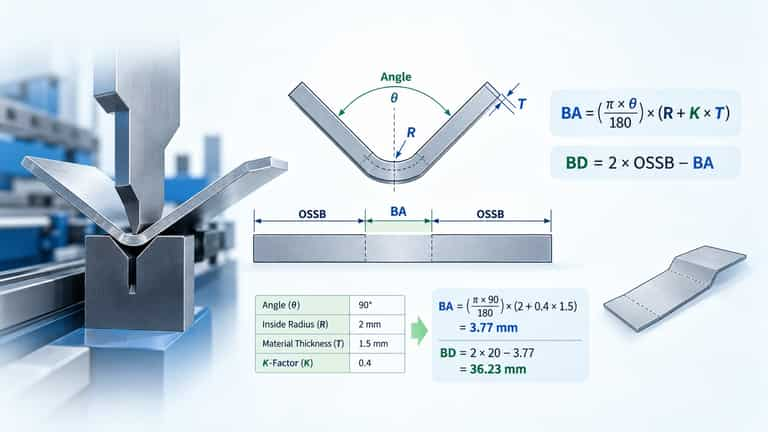
Quick answer: Bend allowance (BA) is the developed arc length through the bend, measured along the neutral axis. Bend deduction (BD) is the amount subtracted from the sum of two outside, virtual-sharp leg dimensions to obtain the flat length. They are different quantities describing the same bend. With one consistent dimensioning convention, they must produce the same blank length:
BA = (π × θ / 180) × (R + K × T)OSSB = (R + T) × tan(θ / 2)BD = 2 × OSSB − BAFlat length = inside-tangent straight 1 + inside-tangent straight 2 + BAFlat length = outside leg 1 + outside leg 2 − BD
Here θ is the angle through which the sheet is bent, not the remaining included angle; R is the actual inside radius; T is thickness; and K is the neutral-axis location divided by thickness. Use degrees only where the equation says degrees; a calculator’s tan must be set to degrees if using θ / 2 in degrees.
For a reproducible 90-degree example with T = 2.00 mm, R = 3.00 mm, K = 0.40, and outside legs of 40.00 and 30.00 mm, the results are BA = 5.969 mm, OSSB = 5.000 mm, BD = 4.031 mm, and flat length = 65.969 mm. Both routes agree to the shown precision. The worked diagrams and arithmetic below show exactly why.
Scope and evidence: The formulas describe idealized constant-thickness bends with a measurable, approximately circular inside radius and a calibrated K-factor. Numerical examples and generated tables in this guide are calculated demonstrations, not laboratory measurements or certified machine tolerances. Real production requires a first-article bend and an approved material/tooling-specific bend table. This guide does not replace the machine manual, tooling load limits, material specifications, or a qualified process engineer’s judgment.
Original image retained unchanged from the previous article. Illustration only; the displayed press brake is not represented as the source of the calculated test data.
Bend Deduction vs Bend Allowance: Which One Should You Use?
A flat sheet does not maintain the same length on its inner surface, outer surface, and centerline when a press brake bends it. The outside surface stretches; the inside surface compresses. Between them lies a neutral surface whose path provides a useful approximation for calculating blank length. The term bend allowance describes that curved neutral-axis path. The term bend deduction describes the correction to be taken away from dimensions measured to the projected outside corner, also called the virtual sharp or outside mold lines.
Suppose a drawing specifies an L-shaped bracket with two outside flange dimensions. Adding those dimensions overcounts the material around their common corner. Bend deduction removes the overcount. Suppose instead that the drawing specifies two straight lengths terminating exactly at their tangency points to the curved region. Those straight lengths exclude the arc, so bend allowance must be added. Both models describe the same physical part when their datum points and angle conventions are consistent.
This distinction is more than vocabulary. Many shops refer informally to their “bend allowance chart” even when the table’s figures are bend deductions. A programmer may import such values into the wrong CAD field, and a cutting operator may then cut a perfectly precise but incorrectly sized blank. The error can repeat across every bend of a cabinet panel. The correct starting question is not “What value is on the chart?” but “What dimension convention does this value correct?”
The official SOLIDWORKS bend allowance and bend deduction documentation explicitly distinguishes the two flat-length expressions. Autodesk’s sheet-metal unfold guidance likewise supports K-factor methods and material-specific bend tables. These resources substantiate the terminology; they do not validate a particular shop’s K-factor or the illustrative numerical values in this article.
| Term | Meaning | Typical input | Formula role | Typical use |
|---|---|---|---|---|
| Bend allowance (BA) | Neutral-axis length of the curved segment | Angle, inside radius, thickness, K-factor | Added to straight tangent lengths | Geometry-first development and CAD |
| Outside setback (OSSB) | Distance from virtual sharp to tangent point along each outside leg | Angle, outside radius (R + T) | Connects outside dimensions to BA | Conversion between BA and BD |
| Bend deduction (BD) | Amount subtracted from two outside dimensions | OSSB and BA, or a validated bend table | Subtracted from outside leg total | Shop-floor outside-dimension drawings |
| K-factor (K) | Neutral-axis offset from inside face divided by thickness | Coupon calibration or approved model | Changes BA and therefore BD | CAD setup and process calibration |
| Flat length (L) | Required developed length of the unbent blank | Consistent leg dimensions and bend data | Output | Cutting and nesting |
Practical decision: If the drawing gives outside virtual-sharp flange sizes, calculate BD or use an approved BD table. If the sketch supplies tangent-to-end straight lengths, add BA. If a CAD system unfolds the complete model, select one validated unfolding method and confirm whether its displayed parameter means allowance, deduction, or compensation. Do not subtract a BD and also add a BA for the same bend; that double-compensates the corner.
Definitions and One Consistent Angle Convention
This guide uses the following symbols throughout. Keeping a visible legend next to a shop worksheet prevents many of the errors attributed to “bad K-factors.”
| Symbol | Definition | Unit | Where measured |
|---|---|---|---|
T | Actual sheet thickness | mm or in | Away from bend and damaged edges |
R | Finished inside bend radius | mm or in | Curved inside surface, after springback |
K | Neutral-axis factor | Dimensionless | Offset from inside face divided by T |
θ | Bend rotation/deflection angle | Degrees | Change in direction of sheet centerline |
φ | Included opening angle | Degrees | Remaining inside angle between straight legs |
BA | Bend allowance | mm or in | Along neutral arc between tangencies |
OSSB | Outside setback | mm or in | Outside virtual sharp to tangent |
BD | Bend deduction | mm or in | Outside-dimension correction |
O1, O2 | Outside flange dimensions | mm or in | Free edge to virtual sharp |
S1, S2 | Straight tangent dimensions | mm or in | Free edge to tangent point |
L | Flat pattern length | mm or in | Unbent blank, along development direction |
In a simple bend whose initial and final straight portions are parallel to the drawing’s ideal tangent lines, θ + φ = 180°. A typical right-angle bracket has θ = 90° and φ = 90°, which makes the distinction easy to miss. A part with a 120-degree included opening has only a 60-degree bend rotation. Insert 60, not 120, into the bend-allowance equation. Conversely, a part folded to a 60-degree included opening has a 120-degree rotation. CAD systems and press-brake programs sometimes label their angle inputs differently, so verify the machine’s convention rather than assuming that an A column has the same definition everywhere.
All length terms must use the same unit. If thickness is in millimeters, radius and legs must also be in millimeters; the output is millimeters. The K-factor is a ratio and stays dimensionless during a metric-to-inch conversion. For radians, the equivalent formula is BA = θ_rad × (R + K × T). The factor π/180 appears only when θ is entered in degrees. Similarly, tan(θ/2) must interpret the angle in degrees; otherwise convert to radians first.
One more important distinction is that a 90-degree bend can be obtained with different punch angles, V-openings, depths, and final radii. The displayed machine angle is not always the final released part angle because springback occurs. The equations use the finished angle and finished radius for the modeled part; the press brake’s programmed forming angle may be different.

Original KRRASS diagram retained unchanged. Use the variable definitions in this guide when reading any legacy label or caption.
Why Metal Changes Length During Bending
Imagine several thin layers running through the thickness of an unbent sheet. When the sheet is formed into a curve, the outer layers travel a longer path than before while the inner layers travel a shorter path. During plastic bending, the location where the longitudinal strain is approximately zero migrates from the geometric mid-thickness. Its location is represented by the K-factor. In the simple geometric approximation, the neutral radius equals R + K × T, so the arc length is angle in radians multiplied by that radius.
The phrase “the sheet stretches” is useful shorthand but can also mislead beginners. The entire bend region does not increase uniformly in length, and bend allowance is not a fixed extra margin appended to the outside dimension. It is the modeled developed length of one portion of the part. When an outside-leg method is used, the curve’s material is already partly accounted for by the virtual-sharp leg dimensions, so a deduction rather than an addition is required.
Three effects make real bending more complicated than a perfect circular arc. First, the cross-section may not maintain constant thickness, especially with tight bends and high plastic strain. Second, the finished profile may contain transitional zones near each tangent rather than an abrupt change from straight to circular. Third, elastic recovery causes springback; a bend that looks correct under load may open after release. For ordinary press-brake planning, a calibrated K-factor or measured bend deduction captures the combined effect well enough for many jobs. For high-precision, unusually thick, high-strength, or noncircular formed parts, a drawing-specific developed-length method may be necessary.
A good engineering practice is to separate what is known directly from what is estimated. Actual thickness can be measured with a micrometer. Inside radius can be checked with suitable gauges or profile measurement. Outside legs can be measured after bending. K-factor is inferred from the resulting geometry and known flat length; it should not be represented as a universal constant for all sheets called “steel” or “aluminum.” Autodesk’s guidance on determining K-factor from trial bends specifically recognizes the need to update it from produced parts.
The Bend Allowance Formula, Derived Step by Step
For a circular bend, arc length is s = r × θ_rad. The neutral-axis radius is r_n = R + K × T. Substituting one into the other gives the standard bend allowance formula:
BA = (π × θ / 180) × (R + K × T)
This equation is not an empirical promise that every grade bends with one predefined K-factor. It is a geometric relationship using an assumed neutral-axis location. The shop’s real engineering work lies in measuring or validating R and K. SOLIDWORKS documents the same K-factor form and defines the factor as the neutral-plane location relative to thickness.
Consider the calculation for a right-angle bend with T = 2.00 mm, R = 3.00 mm, and K = 0.40. First obtain the neutral-axis radius: R + K × T = 3.00 + 0.40 × 2.00 = 3.80 mm. Next convert a 90-degree rotation into radians: 90 × π / 180 = π/2 ≈ 1.570796327. Finally multiply the two: BA = 1.570796327 × 3.80 = 5.969026 mm. Round at the very end, not at each intermediate step.
A quick dimensional check helps detect transcription mistakes. Radius and thickness are both lengths, K-factor has no unit, and radians are dimensionless. The answer must therefore be a length. A formula that multiplies length by thickness, forgets the angle conversion, or produces square millimeters cannot be correct for BA. Another sanity check is that BA gets longer as bend rotation or neutral-axis radius increases, with all other inputs unchanged.
For a 90-degree bend, the simplified expression is BA = (π/2) × (R + K × T). For a 180-degree rotation, it is BA = π × (R + K × T), but forming a true hem may involve flattening, material contact, thinning, or a noncircular shape, so use this arc model for a hem only when its geometry is actually represented by a circular bend. A radius close to zero is another case where a purely geometric formula can be misleading if the material experiences severe thinning or cracking.
Some older references approximate K as about one-third for tight bends and one-half for generous bends. Those are conditional estimation conventions, not alternative physical laws. If a method says to substitute T/3, it is using K = 1/3; if it says T/2, it is using K = 1/2. Do not compute one example with K = 0.42 and claim a second result obtained with K = 1/3 “verifies” it. Those are two models with different inputs. More importantly, a rule declared for R < T cannot legitimately be used without qualification when the test case has R = 2T.
From Bend Allowance to Outside Setback and Bend Deduction
The outside setback is a geometric distance along an outside straight extension from its tangent point to the intersection of the two theoretical outside lines. That projected intersection is the outside virtual sharp. For a bend rotation θ:
OSSB = (R + T) × tan(θ / 2)
Why is the radius here R + T rather than R + K × T? Because setback is measured along the outside surface of the sheet, not along the neutral axis. A diagram drawn at scale shows two right triangles joining the curve to the virtual sharp. Each has one setback distance, so the sum of two outside-leg measurements includes two pieces of geometry extending beyond the two tangencies.
If the straight tangential lengths are S1 and S2, then O1 = S1 + OSSB and O2 = S2 + OSSB. The true developed length is L = S1 + S2 + BA. Replace the tangent terms with outside-leg terms: L = (O1 − OSSB) + (O2 − OSSB) + BA. Rearranging produces L = O1 + O2 − (2 × OSSB − BA).
Therefore the bend deduction formula is:
BD = 2 × (R + T) × tan(θ / 2) − (π × θ / 180) × (R + K × T)
This is the fully expanded expression. The shorter expression BD = 2 × OSSB − BA is identical. A bend deduction should not be confused with “material shrinkage” or an arbitrary kerf compensation; it is specifically the geometric correction required when the quoted flange lengths extend to the theoretical outside corner.
In the example, OSSB = (3.00 + 2.00) × tan(45°) = 5.000 mm. Two setbacks total 10.000 mm. Subtract BA = 5.969026 mm, yielding BD = 4.030974 mm. This number can be stored in a bend table for the defined material, thickness, inside radius, finished angle, and tooling/process conditions. It must not be reused blindly for a different V-opening that produces a different radius.
Important edge case: Setback and deduction are most intuitive for simple, open-angle bends represented by two distinct straight tangent legs and a virtual sharp. At extreme folds or overlapping hem geometries, the projection can extend far beyond useful drawing dimensions. CAD flattening for hems, joggles, rolled edges, beads, or multi-radius bends may require specialized features instead of adding conventional single-bend deductions.
A Reproducible 90-Degree Bracket: The Same Answer Two Ways
The primary worked example is fully specified so a reader can reproduce it using a scientific calculator, spreadsheet, or CAD sheet-metal rule. This is an illustrative design case, not a report of a physical KRRASS-machine trial.
| Input | Value | Interpretation |
|---|---|---|
Finished bend rotation θ | 90.00° | Finished included angle also 90.00° |
Sheet thickness T | 2.00 mm | Uniform nominal and assumed measured thickness |
Finished inside radius R | 3.00 mm | Actual modeled bend radius, not die opening |
Assumed K-factor K | 0.400 | Example input awaiting shop calibration |
Outside flange O1 | 40.00 mm | Free end to virtual sharp |
Outside flange O2 | 30.00 mm | Free end to virtual sharp |
Method A: using bend deduction. Compute BA = (π/2) × (3.00 + 0.400 × 2.00) = 5.969026 mm. Compute OSSB = (3.00 + 2.00) × tan(45°) = 5.000000 mm. Then BD = 10.000000 − 5.969026 = 4.030974 mm. The flat length is L = 40.000000 + 30.000000 − 4.030974 = 65.969026 mm.
Method B: using bend allowance. Outside dimensions must first be converted to tangent dimensions: S1 = O1 − OSSB = 40.00 − 5.00 = 35.00 mm and S2 = 30.00 − 5.00 = 25.00 mm. Add the modeled neutral arc: L = 35.000000 + 25.000000 + 5.969026 = 65.969026 mm.
Cross-check: 65.969026 − 65.969026 = 0.000000 mm before rounding. The agreement is mathematical because the BD expression was derived from the BA expression. It is not independent evidence that K = 0.400 is physically correct for the material. Only coupon measurements can establish how well the predicted 65.969 mm blank produces 40 and 30 mm outside flanges on the intended tooling.
Figure 1. New calculated schematic, not a shop-floor measurement. The dimensions and two development paths correspond to the arithmetic immediately above; drawing is schematic rather than a tool-clearance print.
| Calculation check | Expression | Result (mm) |
|---|---|---|
| Neutral-axis radius | 3 + 0.4 × 2 | 3.800000 |
| Angle in radians | 90 × π/180 | 1.570796 |
| Bend allowance | 1.570796327 × 3.8 | 5.969026 |
| Outside setback | (3 + 2) × tan 45° | 5.000000 |
| Bend deduction | 2 × 5 − 5.969026 | 4.030974 |
| Flat from outside legs | 40 + 30 − 4.030974 | 65.969026 |
| Flat from tangents | (40 − 5) + (30 − 5) + 5.969026 | 65.969026 |
For an actual blank drawing, rounding policy matters. If the cutting process accepts three decimal places in millimeters, record 65.969 mm; if the shop standard rounds blank dimensions to 0.01 mm, use 65.97 mm. The cutting program, inspection plan, and measured first article should follow one declared precision rule. Adding false decimal places does not create process capability.
A Second Worked Example: A 120-Degree Included Opening Is a 60-Degree Bend
Angle conventions cause mistakes even when the BA and BD formulas are written perfectly. Consider another two-flange part made from T = 1.50 mm sheet with R = 2.00 mm and an illustrative K = 0.38. The included opening angle is φ = 120°, while the material has rotated through θ = 180° − 120° = 60°. Suppose the two outside flange dimensions are O1 = 45.00 mm and O2 = 25.00 mm, each measured to the appropriate outside virtual sharp.
First calculate BA = (π × 60 / 180) × (2.00 + 0.38 × 1.50) = (π/3) × 2.57 = 2.691298 mm. Next compute OSSB = (2.00 + 1.50) × tan(30°) = 3.50 × 0.577350269 = 2.020726 mm. The bend deduction is BD = 2 × 2.020726 − 2.691298 = 1.350154 mm. The developed length is L = 45.00 + 25.00 − 1.350154 = 68.649846 mm.
Check the answer with tangent dimensions. The first straight portion is 45.00 − 2.020726 = 42.979274 mm; the second is 25.00 − 2.020726 = 22.979274 mm. Adding the bend allowance returns 42.979274 + 22.979274 + 2.691298 = 68.649846 mm. No new bending rule was necessary; only the correct interpretation of the angle changed.
If an operator mistakenly enters 120° into the bend-rotation field, both arc length and outside setback will change drastically. Because the tangent function grows rapidly at higher angles, the outside-dimension correction may become especially wrong. When drawings specify an angle at the opening, make the conversion explicit in the setup traveler: opening 120° → bend rotation 60°. For unusual folded shapes, confirm which virtual corner the dimension refers to before performing any arithmetic.
| Item | Expression | Result |
|---|---|---|
Included opening φ | Specified by drawing | 120.000° |
Bend rotation θ | 180° − 120° | 60.000° |
| Neutral radius | 2 + 0.38 × 1.5 | 2.570 mm |
| Bend allowance | (π/3) × 2.57 | 2.691 mm |
| Outside setback | 3.5 × tan(30°) | 2.021 mm |
| Bend deduction | 2 × 2.020726 − 2.691298 | 1.350 mm |
| Blank length | 45 + 25 − 1.350154 | 68.650 mm |
Repairing the Inconsistent Formulas in the Previous Article

Original legacy illustration retained unchanged. The recalculated formulas and definitions in the following section supersede any inconsistent notation or numerical statement visible in older graphics.
The earlier version of this KRRASS guide introduced an expression that omitted K-factor and used the full thickness inside the neutral radius: BA = (π/180) × θ × (R + T). Later passages used BA = (π/180) × θ × (R + K × T). These expressions can agree only in the special mathematical case K = 1, which places the assumed neutral axis at the outer surface. That is not the ordinary neutral-axis assumption intended by the subsequent examples. For consistency, the K-factor equation is now the primary equation everywhere in this guide.
The previous worked inch example used T = 0.125 in, R = 0.250 in, θ = 90°, and K = 0.42. Correct arithmetic gives BA = (π/2) × (0.250 + 0.42 × 0.125) = (π/2) × 0.3025 = 0.475165889 in. Rounded to three decimals, this is 0.475 in. That first result was essentially correct.
However, the earlier “advanced” comparison applied a conditional approximation expressed for an inside radius smaller than thickness (R < T) to a case where R = 2T. The stated applicability condition was not met. In addition, replacing K = 0.42 with K = 1/3 yields BA = (π/2) × (0.250 + 0.125/3) = 0.458148929 in, not the previously printed approximately 0.477 in. The second number was a numerical error in addition to an inconsistent model comparison. An approximation that uses a different K-factor cannot independently verify the K-factor used in the first calculation.
| Calculation used in legacy article | Explicit assumptions | Correct BA (in) | Editorial verdict |
|---|---|---|---|
Generalized BA with K = 0.42 | R = .250, T = .125, θ = 90° | 0.475166 | Valid arithmetic for the assumed K |
R + T/3 approximation | Implies K = 1/3; previous R < T condition fails | 0.458149 | Not a valid check for this scenario |
| Earlier printed approximate value | Claimed 0.477 for the second expression | Incorrect | Removed and corrected |
This correction illustrates an important engineering principle: agreement between two formulas matters only if the inputs and modeling assumptions are equivalent. Two wrong values can accidentally look close, and two correct formulas can give different answers when their K-factors or angle definitions differ. The check that really matters is whether the chosen blank produces the specified finished outside dimensions under the actual material and tool setup.
The original article also offered large SPCC/SECC and aluminum tables under the heading “bending allowance.” Their entries were not accompanied by a full definition of whether the number represented BA, BD, a compensation offset, or a shop-specific cut-length adjustment, nor were the necessary tool, angle, radius, and measurement protocols documented. Some numbers are more typical in magnitude of BD than of a neutral-axis BA, but magnitude alone cannot establish their meaning. Accordingly, the former tables should be treated as historical, unverified setup references rather than universal engineering constants. A production manager may keep the original page’s archival data separately until it is remeasured and relabeled; this updated guide provides transparent calculated comparison tables instead.
K-Factor: What It Measures and How to Choose a Starting Value
K-factor is defined here as K = a/T, where a is the distance between the inside surface and the neutral axis and T is the finished sheet thickness used for modeling. A lower K moves the neutral axis toward the inside surface. A higher K moves it toward the center or outer side, increasing the calculated BA for a given R, T, and θ. In the simplified constant-thickness model, a geometric neutral axis within the material gives 0 ≤ K ≤ 1; many commonly used bending calculations select values below 0.5, but that is not a guaranteed bound for every inferred empirical coefficient or software convention.
The most reliable process is to begin with a documented, material- and method-appropriate estimate, then calibrate the value using a trial coupon. Do not infer K solely from a material name such as SPCC, 304 stainless steel, or 5052 aluminum. Different temper, mill batch, grain orientation, bend angle, V-die width, punch nose, and final inside radius can change the needed developed-length correction. A published online chart is useful for preliminary process planning only if its definitions match your own measurements.
Below is a sensitivity table calculated for the same 2.00 mm, 3.00 mm radius, 90-degree example. It is intentionally not called a steel or aluminum K-factor table. It shows what changing K does mathematically while every other input stays fixed.
| Assumed K | Calculated BA (mm) | Calculated BD (mm) | Flat length for 40 + 30 mm outside legs (mm) |
|---|---|---|---|
| 0.30 | 5.655 | 4.345 | 65.655 |
| 0.33 | 5.749 | 4.251 | 65.749 |
| 0.38 | 5.906 | 4.094 | 65.906 |
| 0.40 | 5.969 | 4.031 | 65.969 |
| 0.42 | 6.032 | 3.968 | 66.032 |
| 0.45 | 6.126 | 3.874 | 66.126 |
| 0.50 | 6.283 | 3.717 | 66.283 |
At θ = 90° and T = 2 mm, a change in K of 0.01 changes BA by (π/2) × 2 × 0.01 ≈ 0.031416 mm. For a part with several bends, individual flat-length differences may accumulate depending on the bend arrangement. This explains why a seemingly minor change in a CAD rule can matter for a tight-tolerance assembly. It also shows why the decimal places displayed in a software dialog should not be mistaken for independently verified material behavior.
The Autodesk Inventor K-factor support article recommends correcting the factor from a bent test piece when actual results differ. The SOLIDWORKS K-factor help documents the underlying definition and expression. These independent software references are better authorities for software field meanings than an unattributed web chart; a shop’s bend coupon remains the appropriate authority for its own specific tooling combination.
Figure 2. Calculation-only sensitivity comparison using fixed T = 2 mm, R = 3 mm, and θ = 90°. Not material testing or machine performance data.
Building a Real Bend Table from First-Article Test Coupons
A useful bend table is a controlled record of the relationship between material, tooling, bend geometry, and finished dimensions. The simplest way to build one is to cut a strip with a known developed length, bend it once under normal production settings, measure the resulting outside flange dimensions and final angle, then calculate the measured deduction. Keep the coupon long enough to measure both legs reliably, short enough for safe handling, and representative of the production material. Follow the equipment manufacturer’s safe setup and guarding procedures throughout the process.
- Record the material: grade, specification, temper when applicable, nominal and actual measured thickness, heat or lot when traceability matters, and rolling direction relative to the bend line.
- Record the setup: machine, tool IDs, punch nose radius, V-die opening, tooling condition, crowning or compensation settings, selected air-bending or bottoming method, and programmed angle.
- Measure the blank: record actual cut length
L, not only the nesting software’s target. Remove burrs or note their effect if they interfere with the dimensional datum. - Form and release: bend safely, allow the part to spring back, and check the finished included or rotation angle so the formula uses the correct value.
- Measure finished geometry: measure outside leg dimensions
O1andO2to the agreed virtual-sharp definition. Measure or estimate the actual finished inside radius with an appropriate instrument. - Calculate the effective BD: use
BD_measured = O1 + O2 − L; this definition is direct and does not require first assuming K. - Infer BA and K: calculate
BA = 2 × (R + T) × tan(θ/2) − BD_measured, thenK = [BA/(θ × π/180) − R]/T. - Repeat and approve: bend multiple coupons where precision warrants, check variation, investigate outliers, and store the approved table under controlled revision.
A numerical coupon example makes the inversion clear. Suppose a 100.00 mm flat coupon is bent to a measured finished 90-degree rotation with T = 2.00 mm and R = 3.00 mm. Its two outside dimensions are 51.30 mm and 52.70 mm. Then BD_measured = 51.30 + 52.70 − 100.00 = 4.00 mm; outside setback is still 5.00 mm, giving BA = 2 × 5.00 − 4.00 = 6.00 mm. The inferred K-factor is K = (6.00/(π/2) − 3.00)/2.00 ≈ 0.40986.
This coupon is also a synthetic demonstration. It is not a disclosed KRRASS test record. Its function is to show how a reader can recover an effective K-factor from observable dimensions using internally consistent formulas. For real production, preserve the instrument readings, coupon identifiers, sample size, and final-angle measurements; do not simply type the calculated 0.40986 into every drawing of the same material.
| Sample field | Demonstration value | Why it is needed |
|---|---|---|
| Cut coupon length | 100.00 mm | Independent known flat length |
| Outside legs | 51.30 / 52.70 mm | Determines measured BD |
| Finished rotation | 90.00° | Defines arc and setback geometry |
| Thickness / radius | 2.00 / 3.00 mm | Determines neutral radius and setback |
| Measured deduction | 4.00 mm | O1 + O2 − L |
| Inferred allowance | 6.00 mm | 2 × OSSB − BD |
| Inferred K | 0.40986 | Derived, not independently measured |
A disciplined acceptance procedure should not approve a bend table on a single convenient result. For each important setup, compare repeat samples, both ends of longer bends if crowning is involved, and samples near the edges of the required angle range. If the measured K-factor is wildly inconsistent, investigate the original assumptions: Was the radius measured? Were the flanges referenced to the correct virtual sharp? Did the operator measure the as-formed angle or the drawing’s nominal angle? Is the material thickness consistent? Is the bend truly circular enough for the chosen model?
A table entry should say whether it is a measured BD or an inferred K, and it should name its scope. A practical record might be labeled: “Material grade and temper / T 2.00 mm / V-opening 16 mm / tooling set P03-D04 / finished 90° / measured R 3.0 mm / BD 4.00 mm / sample group B / revision 02.” Even with this metadata, every new material heat, tooling change, or critical tolerance warrants an engineering review rather than an automatic assumption of interchangeability.
The Effect of Bend Angle: A Transparent Calculated Reference Table
People often search for a ready-made bend allowance chart because they want a fast number for the backgauge setup or laser-cut blank. A useful chart, however, must declare its angle convention, thickness, radius, and K-factor. The following table fixes T = 2.00 mm, R = 3.00 mm, and K = 0.40; only bend rotation varies. All values are computed from the three formulas at the beginning, not measured on a machine.
| Bend rotation θ | Included opening φ | BA (mm) | OSSB (mm) | BD (mm) |
|---|---|---|---|---|
| 30° | 150° | 1.990 | 1.340 | 0.690 |
| 45° | 135° | 2.985 | 2.071 | 1.158 |
| 60° | 120° | 3.979 | 2.887 | 1.794 |
| 90° | 90° | 5.969 | 5.000 | 4.031 |
| 120° | 60° | 7.959 | 8.660 | 9.362 |
These figures demonstrate why the included angle and bend rotation must not be interchanged. At a 120-degree rotation, the theoretical outside virtual sharp sits a long distance from the tangent point, so the deduction is much larger. That does not imply the physical curved arc itself suddenly becomes enormous: the neutral arc BA grows linearly with angle at a fixed radius, while setback grows according to a tangent function. A deduction can therefore exceed BA and should not be judged plausible or implausible merely by comparing the two numbers.
Do not use this chart for arbitrary material grades or punch/die combinations. If a material produces a different actual radius or an effective K-factor different from 0.40, its BD will change. Because the data are formula-generated, there is also no stated statistical confidence interval or machine repeatability claim. Its value is auditability: anyone can type the declared inputs into a spreadsheet and regenerate every cell.

Original KRRASS tooling photograph retained unchanged. The selected punch and V-die are important process variables; the photograph is not proof of the theoretical table’s numerical values.
Press Brake Tooling Changes the Actual Radius—and the Flat Pattern
The bending calculation needs the finished inside radius. The lower V-die opening is not itself that radius. Under common air-bending conditions, the opening strongly affects the naturally formed radius, but the relationship depends on material behavior and process conditions. The punch nose can matter more in bottoming or coining, where the tool deliberately drives the radius. Tool choice also affects minimum flange support, surface marking, required tonnage, and collision risk.
That is why a quote for a new CNC press brake should not ask only for nominal capacity. The machine, punch, die, controller, and process form one system. KRRASS’s press brake tooling guide explains how punch shapes, die openings, material thickness, bend radius, and flange sizes interact. The KRRASS press brake tonnage calculator is a useful separate planning aid for checking approximate force and V-opening options. Tonnage calculations are not a substitute for measuring BD, and a flat-length equation cannot by itself establish whether a bend is safe or possible on a given machine.
In air bending, a wider V-opening often reduces the bending force while increasing the natural inside radius and the minimum flange needed for stable support. If the nominal 2 mm sheet in our example bends at R = 3 mm on one die but closer to another radius after a tool change, reusing the old deduction will propagate an error into the blank. In bottoming, the finished inside profile may be controlled more directly by the tool nose, but tool load ratings, material behavior, and springback still need validation.
Tool selection should therefore occur before bend-table approval. Record the V-opening, punch nose radius, machine method, and finished radius, then establish a BD or K value for that combination. For short flanges, make sure the workpiece will remain supported by the die; for deep boxes and return flanges, verify collision clearance; for cosmetic panels, consider surface protection. These practical constraints can force a different tool, and a different tool can force a different developed length.
The original article’s machine schematic is kept below as supporting equipment context. Its function is to help readers visualize where bending occurs, not to substitute for a dimensioned section of the worked bracket.

Original SVG retained at its source URL without alteration. Some WordPress editors may require an SVG-permitted media policy; if SVG is blocked, use the original article’s existing CMS attachment instead of converting or redrawing it.
Multiple Bends: Calculating a U-Channel or Cabinet Profile
The formulas extend from one bend to multi-bend parts, but the drawing’s dimension chain becomes more important. A U-channel may show a left wall, a web, and a right wall. If these are drawn as consecutive outside virtual-sharp dimensions, a first approximation is the sum of those dimensions minus the bend deduction for each bend: L = O1 + O2 + O3 − BD1 − BD2. It is not valid to sum dimensions that have already been projected to different datum conventions or to subtract a deduction for a corner already represented by an explicit tangent arc.
Assume a simple open U-channel with three consistently defined outside segments of 30.00 mm, 80.00 mm, and 25.00 mm. It has two finished 90-degree bends, and for the sake of illustration each bend uses T = 2.00 mm, R = 3.00 mm, and K = 0.40. We already calculated BD = 4.030974 mm for each identical bend. Thus L = 30.00 + 80.00 + 25.00 − 2 × 4.030974 = 126.938052 mm. If the web geometry, bend radii, or angles differ, calculate each BD_i separately rather than multiplying one convenience value by the number of bends.
| Segment or bend | Input / deduction (mm) | Running developed length (mm) |
|---|---|---|
| Outside segment 1 | +30.000000 | 30.000000 |
| Outside segment 2 | +80.000000 | 110.000000 |
| Outside segment 3 | +25.000000 | 135.000000 |
| Bend 1: 90°, R3, T2, K0.40 | −4.030974 | 130.969026 |
| Bend 2: 90°, R3, T2, K0.40 | −4.030974 | 126.938052 |
A real channel also raises questions not captured by the length equation: Is the middle web dimension measured outside-to-outside or inside-to-inside? Does the drawing dimension from the projected sharp or actual radius tangencies? Can the second flange pass the punch and tool holders during the chosen sequence? Will springback at the first bend affect gauge contact for the second? A mathematical development can be internally consistent yet impossible to form with the available tooling.
For enclosure panels with four or more bends, use a controlled CAD flat pattern as the master geometry and compare one representative first article with its dimensional inspection record. If the controller calculates its own unfolding compensation, avoid applying another independent BD table in CAM unless the workflow explicitly requires it. Version-control the selected rule so the designer, laser programmer, and press brake operator do not unknowingly apply different compensations to the same job.
CAD and CNC Controllers: Avoid Double Compensation
Many modern design packages let the engineer choose a K-factor, bend allowance, bend deduction, bend table, or custom unfolding equation. The options are not arbitrary synonyms; they are alternative methods of defining how the model should develop. SOLIDWORKS documentation lists these alternatives, while Autodesk explains material-based bend tables that can reflect nonlinear process behavior better than a single uniform K-factor.
A safe CAD workflow begins by confirming what the drawing actually dimensions. Model the correct sheet thickness and the intended finished inside radius. Verify the bend rotation rather than copying an included angle into the wrong field. Choose the unfolding method approved for the material and forming process. Generate the flat pattern once, compare it to a manual calculation on one simple representative bend, and save the sheet-metal rule name in the manufacturing documentation. If a machine controller offers angle compensation or springback correction, distinguish these controls from the developed-length rule: angle correction changes the formed angle, whereas BA/BD controls the blank length needed for the specified finished geometry.
When an engineer exports a DXF for cutting, verify whether the file contains actual flat geometry or merely bend annotations. If the DXF already contains a fully unfolded outline, applying further outside-leg deductions in the laser program shrinks the blank a second time. Likewise, if a supplier issues a dimensioned flat pattern, do not rebuild the cut length from a bent-part drawing unless there is a documented reason to do so. Manufacturing data should identify its authority: 3D master, approved flat DXF, or shop-developed manual layout.
For teams comparing equipment, the KRRASS CNC press brake product overview explains the broader machine category, while the KRRASS tooling selection guide discusses the importance of punches and dies. Neither link is intended to imply that a controller can calculate an accurate blank from unspecified material and tool conditions. Even sophisticated software relies on trustworthy geometric and process inputs.
Material Grade, Grain Direction, and Springback
Material changes the relationship between nominal CAD geometry and the produced part. Mild steel, stainless steel, aluminum alloys, and copper alloys can differ in strength, ductility, elastic recovery, and achievable radius. Even two sheets of the same nominal grade may differ in actual thickness, temper, surface coating, or rolling-direction properties. These differences affect bend feasibility and the best effective compensation, especially when the part requires tight tolerances.
For SPCC or other cold-rolled sheet, the material specification and actual lot matter more than a generic internet row headed “steel.” Zinc-coated sheet can also bring surface and thickness measurement considerations. Stainless steel often requires greater forming force and may exhibit more springback than a mild-steel setup, depending on grade, thickness, and bend geometry. Aluminum is not one material: temper and alloy can radically change formability; an inappropriate small radius may crack a hardened alloy even when the BA equation returns a neat numerical length. Copper and brass require their own process validation, especially for visible finishes or sharp small-radius work.
Rolling direction matters because forming across versus along the grain can influence cracking risk and performance. However, it is not meaningful to put one universal “grain direction correction” into the bend allowance formula. Instead, record orientation in the coupon data and test the configuration that production will actually use. If the drawing specifies a minimum inside radius or an orientation restriction, those constraints take precedence over optimizing blank yield by choosing a convenient die opening.
Springback must be separated conceptually from the bend-length calculation. The punch may need to travel beyond the nominal finished angle to achieve that angle after release. For the flat pattern, use the resulting finished radius and bend rotation where the adopted model calls for them. If the formed part changes dimension after removal from the machine, remeasure before adjusting the K-factor. Correcting a springback error by changing K can make the flat pattern appear better in one measurement while leaving the underlying angle error unresolved.
Where fabrication tolerances are contractually critical, obtain material certification as required, confirm the drawing’s inspection datum, and agree on acceptance criteria before production. Neither an online material chart nor the calculations in this article establish a guaranteed radius, minimum safe bend angle, or permitted load. These must be addressed through manufacturer information, tooling load charts, applicable specifications, and validated engineering tests.
Understanding Tolerance and Measurement Uncertainty
A formula can be exact algebraically while its inputs are uncertain. In a typical shop, nominal T = 2.00 mm does not guarantee that the sheet measures exactly 2.000 mm everywhere. The inside radius may not be perfectly circular, the angle may differ along a long part, and it can be difficult to construct a repeatable virtual-sharp measurement without a defined inspection method. For that reason, the last few digits of a computed BA should not be described as production accuracy.
Sensitivity analysis helps show which inputs deserve attention. From BA = θ_rad × (R + K × T), the local sensitivity to K is ∂BA/∂K = θ_rad × T, and the sensitivity to R is ∂BA/∂R = θ_rad. At 90 degrees and 2 mm thickness, an error of 0.05 in assumed K changes BA by about 0.157 mm; a 0.10 mm error in radius changes BA by about 0.157 mm as well. These are calculated one-variable effects, not total tolerances for a finished part.
The angle also matters. BA itself changes with bend rotation, while setback contains tan(θ/2) and becomes increasingly sensitive at more closed folds. BD is therefore sensitive to both geometry and angle. A shop dealing with acute included angles should avoid transferring a 90-degree deduction unchanged and assuming the controller will somehow correct the blank length. It is safer to calibrate the intended finished-angle range using an approved bend table or representative coupons.
When documenting a first article, record the nominal value, actual measurement, measuring tool, operator, date, and acceptance criterion. Use repeat measurements if the inspection method has appreciable scatter. If two operators cannot reproduce the same flange reading, investigate the datum and fixture rather than changing software parameters until one reading looks convenient. For an assembly with several bends, check the dimensions that matter to mating parts, not only the total flat length.
Finally, separate process capability from geometrical reproducibility. The mathematical cross-check in this article proves that two correctly transformed geometric formulas agree. It does not prove that a machine can repeat a flange to ±0.05 mm, that a steel grade has a fixed K-factor, or that a complex bracket will be free of twist, bow, crowning variation, or collision. Those require physical validation and, where appropriate, statistical process evaluation.
Practical Spreadsheet Formulas for a Repeatable Bend Worksheet
A shared workbook can prevent arithmetic mistakes if it clearly labels every input and includes a cross-check. One simple layout uses cells B2 = θ in degrees, B3 = R, B4 = T, B5 = K, B6 = O1, and B7 = O2. Use the formulas below in Excel or Google Sheets; their trigonometric functions accept radians, so RADIANS() is necessary.
| Cell | Description | Spreadsheet formula |
|---|---|---|
| B8 | Bend allowance | =RADIANS(B2)*(B3+B5*B4) |
| B9 | Outside setback | =(B3+B4)*TAN(RADIANS(B2/2)) |
| B10 | Bend deduction | =2*B9-B8 |
| B11 | Flat from outside legs | =B6+B7-B10 |
| B12 | Flat from tangent lengths | =(B6-B9)+(B7-B9)+B8 |
| B13 | Arithmetic difference | =B11-B12 |
When the spreadsheet is entered correctly, B13 is zero apart from floating-point rounding. A nonzero result indicates a spreadsheet reference, conversion, or formula problem, not a need for an experimentally different K-factor. Add data validation so the user cannot accidentally enter a negative thickness or a rotation angle incompatible with the chosen geometry. For a more robust system, lock the formula cells, require a material/tooling rule ID, and display whether the selected coefficient is provisional or approved.
A second sheet can hold coupon records and approved deductions. Each row should store material ID, actual thickness, finished rotation, measured radius, tooling, original coupon length, observed outside legs, calculated measured BD, inferred K, and approval status. One source of truth is preferable to independent copies of spreadsheets maintained by engineering, cutting, and bending teams. Any update should record why it changed and which drawings or orders must be rechecked.
For laser cutting and nesting, export the final approved developed profile rather than manually transcribing only a length when geometry includes reliefs, holes, slots, or notches. A flat length is just one dimension of a blank. Holes near bends may distort; bend relief geometry may change edge development; corner cutouts and hems need additional rules beyond a single BA value.
Frequent Bend Allowance and Bend Deduction Mistakes
Mixing outside and inside dimensions. BD belongs to the declared outside virtual-sharp convention. Applying the same BD to measured inside flange lengths normally gives the wrong development. Redraw the section with tangent points and virtual sharp points before recalculating. If a supplied print contains mixed dimension types, convert them into a consistent chain rather than guessing which numbers are “close enough.”
Treating included angle as bend rotation. A 120-degree opening is a 60-degree rotation. This changes both BA and OSSB. For training, mark both angles on a typical drawing and have the operator reproduce the calculation before using a bend chart.
Entering V-die width as inside radius. A V16 marking describes the nominal die opening, not R = 16 mm. The finished radius requires a separate value based on method and the material/tool combination. A wrong radius may have a larger effect than a minor K-factor discrepancy.
Copying one material K-factor to every bend. A single K-factor can be a useful initial CAD rule, but changing thickness, radius, temper, bending method, or drawing tolerance may require a new validation. Complex part families may need a bend table rather than one constant.
Believing the first sample proves repeatability. A coupon checks one condition at one moment. It does not quantify long-term process variation, material batch effects, tool wear, or angle drift. Where dimensional risk is high, repeat the test and establish a suitable approval process.
Rounding too early. Rounding BA to one decimal before calculating BD can move the final cut length, especially when deductions accumulate over several bends. Keep full calculation precision, round final manufacturing outputs according to the approved drawing standard, and measure the first article.
Using unsafe tooling to achieve a calculated radius. Geometry alone does not authorize a tool setup. Follow actual tooling load limits, minimum-flange guidance, guarding requirements, and the press brake operating manual. The U.S. OSHA powered press brake machine-guarding guidance describes hazards involving point-of-operation access, foot controls, and moving workpieces. Safety precautions belong in the work instruction, not as an afterthought to optimization.
Failing to document the chosen method. A CAD model using K-factor, an old spreadsheet containing BD, and a controller with additional compensation can disagree without anyone knowing why. Add a small note to the drawing or route sheet stating the authoritative blank source and the effective bend rule revision.

Original KRRASS technical figure retained unchanged. Its visual emphasis on the neutral axis and outside setback supports the distinction between BA and BD; this article’s symbols and numeric examples are authoritative for the current explanation.
Frequently Asked Questions
Is bend allowance the same as bend deduction?
No. Bend allowance is the neutral-axis arc length inside the bend. Bend deduction is the correction subtracted from two outside virtual-sharp flange dimensions. For a simple bend with the conventions used here, BD = 2 × OSSB − BA. Both methods should generate identical flat lengths after the leg dimensions are converted correctly. A shop may colloquially call its deduction table an allowance chart, so always verify what the numbers represent.
What is the bend allowance formula for a 90-degree bend?
For a finished 90-degree rotation and a circular inside radius, BA = (π/2) × (R + K × T). For example, R = 3 mm, T = 2 mm, and K = 0.40 give BA ≈ 5.969 mm. This is a calculated value conditional on the K-factor; it is not an automatically certified value for every 2 mm sheet.
How do I calculate bend deduction from bend allowance?
Find the outside setback with OSSB = (R + T) × tan(θ/2) and calculate BD = 2 × OSSB − BA. For a 90-degree rotation, tan(45°) = 1, making OSSB = R + T. With R = 3 mm, T = 2 mm, and BA = 5.969 mm, BD equals approximately 4.031 mm.
Should I add or subtract the bend allowance from the flange lengths?
Add BA only when the two other lengths are measured to the bend’s tangent points and therefore exclude the arc. When using outside virtual-sharp flange dimensions, subtract BD instead. Never add BA directly to the sum of two outside legs unless you have performed a different, explicitly justified conversion; doing so usually makes the blank too long.
What K-factor should I use for mild steel, stainless steel, or aluminum?
There is no universal, guaranteed number based solely on the material family. Choose a documented provisional value suited to the process, then calibrate it by bending and measuring representative samples. Production inputs should account for actual thickness, inside radius, tool geometry, bend method, angle, and material lot. Use a validated bend table when a single global factor does not reproduce the required finished dimensions.
Does a larger inside radius require more bend allowance?
At fixed thickness, K-factor, and bend rotation, yes. The neutral-axis radius R + K × T increases with R, so BA increases linearly. BD also changes because the outside setback increases. The relationship is only a geometric prediction until the radius and effective factor have been checked on the chosen tooling.
Can bend allowance be negative?
For a positive bend rotation and a physically positive neutral-axis radius, the arc-length BA used here is positive. A software field may display a negative compensation or offset depending on its convention; that should not be silently relabeled as negative arc length. Check the CAD package’s documentation and the direction of the correction before transferring values.
Why does my CAD flat pattern disagree with a press-brake chart?
Check whether the chart stores BA or BD, whether it expects included angle or rotation, which radius it assumes, and whether the CAD model uses a fixed K-factor or a bend table. Then compare actual thickness and the tool setup used to produce the chart. A discrepancy may arise from rounding, double compensation, or process changes rather than an inherent error in CAD.
What if a drawing gives two inside flange measurements rather than outside measurements?
Do not directly apply the outside-dimension BD equation. Identify the section geometry and transform the measurements to a consistent tangent or outside virtual-sharp system first. Because the transformation depends on the inside/outside datum locations and the angle, an unlabeled “A + B − BD” shortcut can be invalid. A dimensioned section or correctly modeled 3D part is the safest starting point.
Do these formulas apply to hems, joggles, or large-radius multi-stage bends?
Only insofar as the geometry really consists of circular arc segments and straight tangents represented by the model. Flattened hems, offset joggles, rolled edges, coined corners, and multi-hit large-radius bends may have contact, thinning, or noncircular profiles not captured by one BA and one BD. Use dedicated CAD features or tested developed lengths for those cases.
How accurate are online bend calculators?
A calculator can be mathematically accurate with the inputs entered while still being wrong for production. Input definitions, final radius, K-factor, and the measured part all matter. Compare outputs against a manual worked example, document the assumptions, and verify at least one representative first article before releasing a critical production batch.
How should I verify an old SPCC or aluminum bending table?
Pick a row whose thickness, V-opening, angle, and material can be reproduced. Identify whether its number is claimed as BA, BD, or a cut-length offset. Make a safe, documented trial bend with known flat length, measure outside legs and final geometry, and calculate the observed BD. If the table’s definition or origin cannot be established, label it legacy/unverified and do not use it as a controlling value for new production.
A Practical Approval Checklist Before Cutting the Production Batch
A reliable workflow is deliberately simple: identify the drawing datum, use the finished angle and radius, select one consistent model, calculate the blank, make a coupon, compare the finished part, and approve or revise the rule. The sophistication of the CNC controller does not remove the need to communicate those decisions. For a production release, engineering and manufacturing should agree on the following evidence:
- The drawing identifies material grade, thickness, radius, finished angles, significant flange dimensions, and inspection datums.
- The development method is specified: approved CAD K-factor, measured BD table, or another controlled rule.
- The chosen tool setup satisfies capacity, load, flange-support, guarding, and clearance requirements.
- The calculated flat pattern and the source of its values are identified by part and revision.
- The angle convention is visible, especially for non-90-degree bends.
- A representative first article has been measured, and any required adjustments have been approved.
- The laser or other cutting program uses one authoritative flat pattern and does not reapply compensation.
- The final inspection records the critical dimensions after forming and springback.
For purchasing teams or production managers assessing new equipment, this checklist also clarifies which features to discuss with a supplier: consistent backgauge positioning, tooling compatibility, crowning, controller workflow, support for controlled bend rules, and operator training. KRRASS provides CNC press brake information, a practical punch and die selection guide, and a separate bending tonnage calculator to support that wider conversation. Product selection should still be based on drawings and application requirements rather than treating this flat-length equation as a machine capacity assessment.
Conclusion: One Bend, Two Equivalent Calculation Routes
The clearest answer to bend deduction vs bend allowance is that they are not competing measures of how metal stretches. BA describes the modeled developed length of the bend arc. BD corrects the overcount introduced by outside virtual-sharp dimensions. The link between them is the outside setback. Once the drawing convention is fixed, their equations are simply two algebraic descriptions of the same geometry.
Use BA = (π × θ / 180) × (R + K × T), OSSB = (R + T) × tan(θ/2), and BD = 2 × OSSB − BA. For a 2 mm sheet with a finished 3 mm inside radius, 90-degree rotation, and illustrative K-factor 0.40, a bracket with 40 and 30 mm outside legs develops to 65.969 mm. Subtracting BD from the outside legs and adding BA to the straight tangents gives exactly the same result. This traceable cross-check is more useful than repeating two unrelated approximate formulas and declaring their numbers close enough.
For real manufacturing, the final step is empirical verification. Measure a trial bend made with the planned material and tooling, verify finished angle and radius, establish the effective BD or K-factor, and preserve the approved rule for future parts. That combination of clear mathematics, source-aware definitions, and shop-floor evidence is what turns a bend allowance formula into a dependable production process.
Share